
HEADS Site – Infra Features for various project development and construction work, for Land Acquisition and maintenance of Land records and drawings, Site Leveling and Grading to prepare for construction platforms for Plants, Design of roads and Tunnels, etc.
Cloud based Process / Storage / Sharing facilities are available as optional. On procuring multiple licenses, say, four licenses, and installing at four different locations anywhere in the country/world, the project name, user name and password may be shared with those four license locations. They all can access cloud server to view the design and drawings, modify, re-process, download, upload the work at the cloud storage ‘Techsoft Drive’.
Website: www.techsoftglobal.com
Email: techsoftinfra@gmail.com, techsoft@consultant.com
Tel: +91 9331 9330 39, +91 33 4008 3349, +91 33 4603 6129
Page 1 off 24
Page 2 off 24
Applications for Projects :
Applications for Engineering Design :
Special Points on Technical Specifications:
Page 3 off 24
Topographical Survey or Satellite Data Processing
Computer applications are very effectively helpful in every stage of Highway development projects starting from Conceptual phase to Preliminary design, to Detail engineering to Construction. The collecting and processing of ground survey data is the first step in computer aided highway design. The process includes creating of ground model, Digital mapping to create the survey base plan, triangulation to create the Digital Terrain Model or DTM and thus the ground Contours and finally the ground long and cross sections.
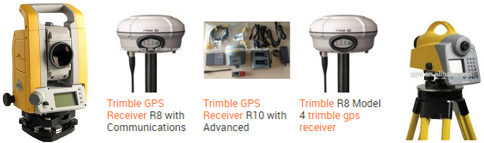
The collecting of ground data uses either obtaining the field survey data most commonly by using the Total Station instrument or obtaining the ground elevation data with the latest available satellite based technology which also helps in identifying the best possible route of the road, its realignment and the widening scheme.
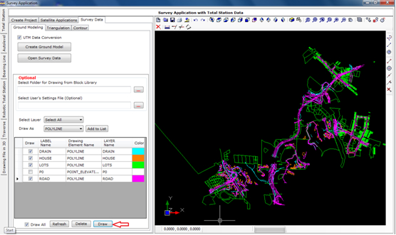
Ground Modeling
The Survey data whether by Total Station survey or by Satellite data, but the data must be made available in the desired format of five columns for: Serial Number, Easting (metres), Northing (metres), Elevation (metres) and Feature Code and saved as a text file (for example SURVEY.TXT) which can be opened in ‘Notepad’. In its has five columns of data, when a data record with Serial No. ‘0’ is met then it discontinues the last feature and reads a new feature in the Ground Model. After creating the ground model it is drawn to create the survey base map and is described in the relevant section of this book.
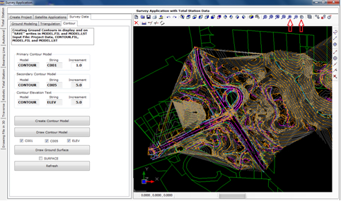
Triangulation and Contours
The model Name, String Label and increments for primary, secondary and Text are set with default names & values. If the ground is of flat nature then user has to reduce the primary contour increment as 0.5 or 0.1 to get contours for the relatively flat ground. The secondary contour increment is always five times of increment of the primary contours. Texts for contour elevations are displayed on the secondary contours.
Tutorial Videos
The various Tutorial Videos are available to understand and master the above processes by watching the Tutorial Videos and next by operating software HEADS Site by following the steps as described in the User’s Guide.
Page 4 off 24
Processing of Topographic Survey Data by Total Station instrument
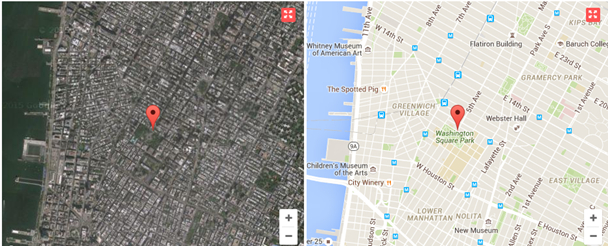
The project corridor may be identified by site reconnaissance survey and by using Topographic maps along with satellite imageries by using Google Earth, as well.
The ground elevation data may be either obtained by Total Station Survey or by downloading from SRTM (Shuttle Radar Topography Mission) by using internet. User may procure the computer program Global Mapper to download ground topography data from internet. Most widely the softwares use Total Station Survey Data for processing Topographical details most effectively and economically in various highway construction projects.
The next job is to prepare the Survey Base Plan or Ground Model from the ground survey data with Total Station. By selecting drawing feature symbols from CAD Block library, the various texts obtained from the surveyors are also placed correctly in the Base Plan drawing. The drawing is made in CAD layered system and is compatible to AutoCAD and other popular CAD softwares.
Finally the Digital Terrain Model (DTM) is created by using the Total Station survey data by Triangulation and subsequently processed for contouring.
Page 5 off 24
Processing of Cross Section Survey Data by Auto level instrument
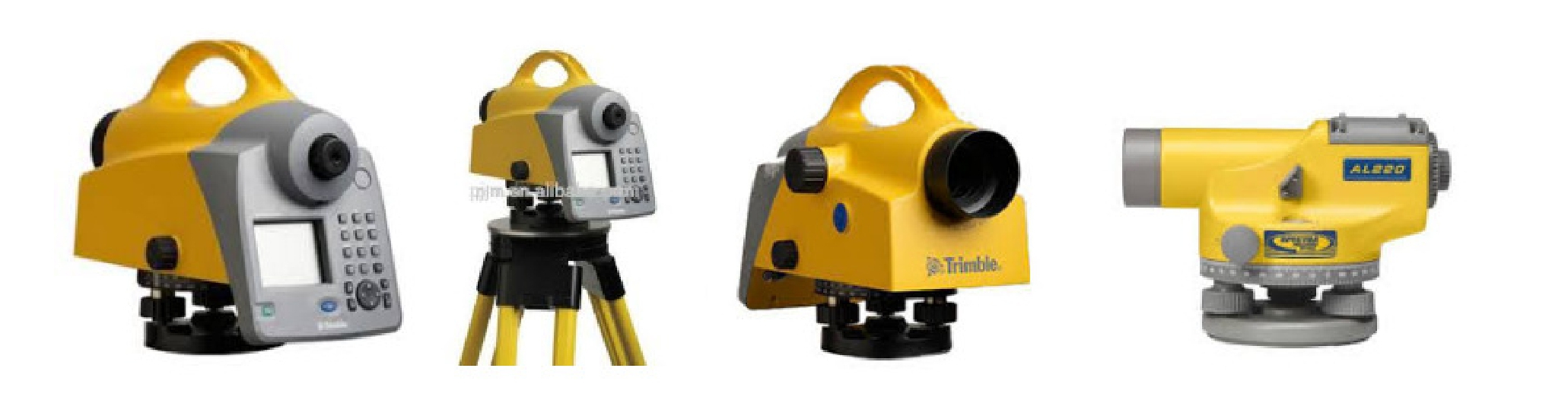
The Autolevel data contains Chainages at a regular / constant interval, the distances on the cross section on either side of the centre point 0.0, left side in ‘-ve’ & right side is ‘+ve’ and the elevations (Z) at all distances on either side of the centre point. The data do not have Easting (X) and Northing (Y) at these points where (Z) is available. So, to get Easting (X) and Northing (Y) at these points an alignment is to be defined, which passes through the centre point at ‘0.0’ of the cross sections at every chainage. The alignment must have the chainages at intervals same as that in the Autolevel Cross section survey. Referring to this alignment the program will obtain the X & Y Coordinates of each point on the cross section, this helps in making Triangulation, Digital Terrain Model and finally the Contours of the ground. Only the survey base plan drawing by digital mapping will not be created from ground model, which needs Total Station data for reading various features like Houses, Drains, Electric Poles, Boundary walls etc. on the ground.
Processing of Bearing Line Survey Data
The Bearing Line method of survey is very widely used in the design of hill roads. Every hill road commonly has hill on one side and valley on the other side. In Bearing Line Survey the traverse passes through the foothill side, which changes its side with respect to the road to stick to the hill.
Page 6 off 24
Processing of Ground Elevation Data by Satellite downloaded from internet
By defining tentative alignment by drawing straights by “My Path” in Google Earth to define the project corridor and subsequently downloading ground elevation data by using Global Mapper minimizes the exercise to transform the Surveyors coordinates in TM (Transverse Mercator) into Global Coordinates in UTM (Universal Transverse Mercator) / GPS. The alignment file may be saved as KML/KMZ file. This file may be opened in future in Google Earth to mark various features along the corridor, for example, the road alignment with existing ‘Land-use’ etc. The area may also be identified or verified by site reconnaissance survey or by using Topographic maps or by procuring satellite imageries from the survey department.
Next, the KML/KMZ file may be opened with Global Mapper and saved as DXF file. Also, the ground elevation data may be downloaded with Global Mapper from SRTM (Shuttle Radar Topography Mission). The DXF file of the alignment is opened in HEADS Viewer and the alignment geometrics are design as Horizontal Alignment of the project highway.
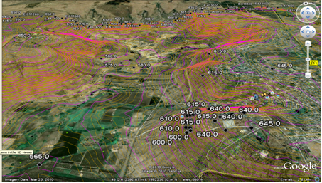
The downloaded ground elevation data is to be opened with software MS-Excel for saving in the desired format. Next the ground data is opened with software HEADS Site to create the ground model, and next the Digital Terrain Model along with contours are to be generated for the entire area under the study. This enables the engineers to Develop the Survey Base Plan, Digital Terrain Model (DTM) by Delauny Triangulation, Ground Contours at user given primary & secondary intervals, 3D Surface with rendering, Ground Long and Cross Sections. The Digital mapping facility by drawing ground model enables the users to prepare Survey base Plan drawings over Google Pictures using the CAD engine of software HEADS Site.

The contour are superimposed on the satellite imagery
The ground survey work also includes obtaining of Traverse coordinates with closing error correction by Bowditch, Transit & Close Link methods, EDM Survey, Coordinate Transformation from WGS84 to Lambert Conformal Conic Projection (Long Lat to East North) and the reverse with Spheroid Everest 1956. This enables to install Survey reference pillars along the proposed highway route for their reference during the construction.
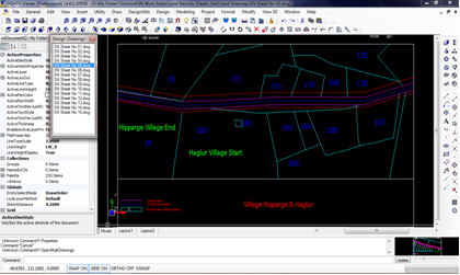
Software HEADS Site will be applied for the design of highway widening with reference to an existing road with multiple cross sections and multiple alignments, where the road cross sections may change with different configuration and with the change in widening pattern from Left to right to concentric along the route from origin to destination. The design has special treatment in hill stretches. Provision for tunnels is also possible with very special design techniques.
Page 7 off 24
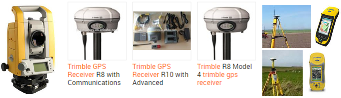
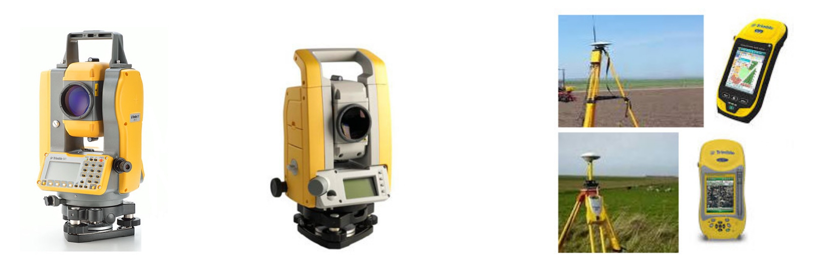
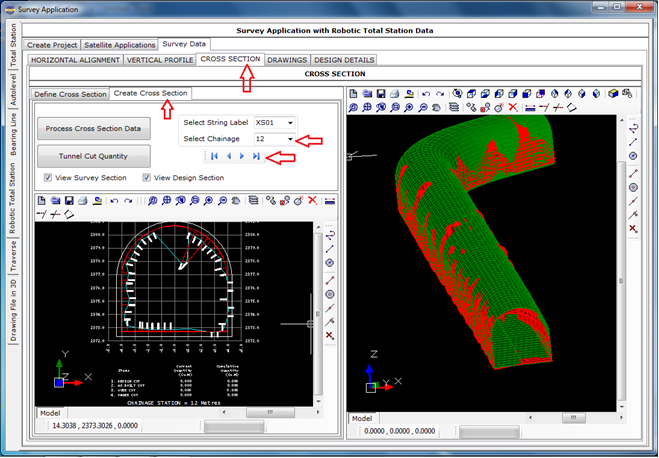
Processing of TRIMBLE Robot Total Station Data
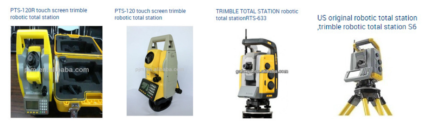
The TRIMBLE Robot Total Station survey data is very widely used in the construction of Bored Tunnels. This is to be noted that the survey is carried out after the boring is done for the tunnel, by following the design horizontal alignment, vertical profile and proposed cross section for the tunnel. The survey data is used to estimate the actual boring against the design cross section of the tunnel. At every chainage the As-Biult and Design Cross Sections are plotted. From the cross sections the ‘Under Cut’ and ‘Over Cut’ quantities are computed by comparing the as-built against the design cross section. Some times in case of excessive overcut the cut quantity is considered up to certain extent outside the design cross section, which is marked as the ‘Pay Line’. Proper measures are to be taken to restore all the over cuts and to remove unwanted soil/rock at the under cuts to match the bored cross sections with the design cross section. All these actions can be done by using the Robotic Total Station survey data and thus processing by HEADS Site to generate cross sections and quantities for Design Cut, As-built Cut (Under Cut & Over Cut) and the Pay Line, also by creating CAD drawings and detail report.
Page 8 off 24
Processing of Traverse Survey Data
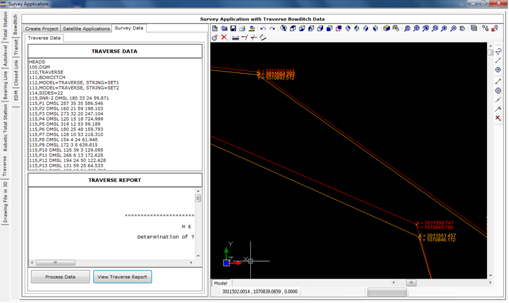
HEADS Site generates Traverse Report describing corrected Traverse and its coordinates with closing error corrections by Bowditch, Transit and Closed link, with EDM applications.
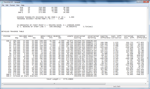
The HEADS Site CAD view of drawing with uncorrected and corrected Traverse and its coordinates.
Page 9 off 24
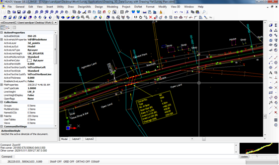
Processing of Drawing File in 3D to extract ground data
The survey plan drawing is made in 3 Dimension and the processing is done to extract the Layer wise x,y,z data of various features of the drawing. The data is saved as Text data in Total Station format and created model with string labels taking from the layer names by saving in the model files.
Ground Modeling
The data in the Total Station survey data file must be made available in the following format and saved as a text file (for example SURVEY.TXT) which can be opened in ‘Notepad’. It has five columns of data, when a data record with Serial No. ‘0’ is met (as after Serial No. 5) then it discontinues the last feature and reads a new feature (from Serial No. 1) in the Ground Model.
Page 10 off 24
Triangulation and Contours
The model Name, String Label and increments for primary, secondary and Text are set with default names & values. If the ground is of flat nature then user has to reduce the primary contour increment as 0.5 or 0.1 to get contours for the relatively flat ground. The secondary contour increment is always five times of increment of the primary contours. Texts for contour elevations are displayed on the secondary contours.
LAND RECORD MANAGEMENT SYSTEM
Relational Data Base Management System (RDBMS with MS Access) is used with HEADS CAD Viewer
For any site development project for Township, Industrial Plants, Roads, Airports, Housing projects the Acquisition of Land for the site is the next job for preparing for construction. The list of names of the land owners, Land category, Land Plot ID, Plot Number, reference District and State in the country. The owners of the acquired land plots are paid by the project authorities. A proper storage of the details along with land maps are therefore essential for the project. The record details are maintained in Relational Data Base Management Systems (RDBMS) and all the land maps as CAD Drawings. The built-in CAD engine is highly powerful with complete drafting and editing facilities. The drawings are compatible to AutoCAD and all other popular CAD softwares.
Page 11 off 24
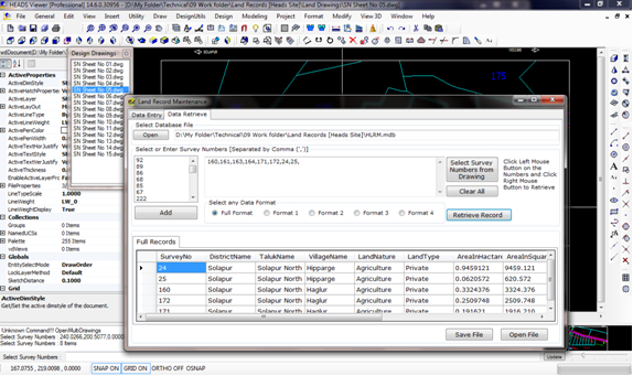
Land records may be Entered and stored in MS Access Database format and CAD Drawings
For any Site preparation the land records and land maps in the existing ground are most essential and properly coordinated by HEADS Site. The establishment of correlation between the database records and the related drawings are extremely useful facilities for maintaining the land records by the users.
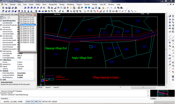
Land records may be retrieved in various specified formats from database or drawings. The relationship between the land map drawings and related records in database management system is highly useful for land record maintenance.
Page 12 off 24
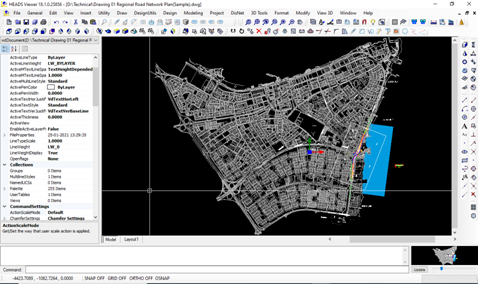
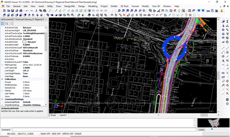
PROCESSING OF DOWNLOADED GROUND ELEVATION DATA
HEADS Site minimizes the exercise to transform the Surveyors coordinates into Global UTM / GPS Coordinates using in-built CAD engine, next the transformed drawing may be opened for conversion to KML/KMZ file to open in Google Earth to define the road alignment for Site Layout, Green Field alignments, Bypasses and Realignments as larger area with existing Land use are visible. The area as identified by site reconnaissance survey, by using Topographic maps and satellite imageries. Next, the ground elevation data may be downloaded from SRTM (Shuttle Radar Topography Mission) and Digital Terrain Model along with contours may be generated for the entire area under the study. This enables the engineers to Develop the Ground Model, Digital Terrain Model (DTM) by Delauny Triangulation, Ground Contours, Ground Sections at user given primary & secondary intervals, 3D Surface with rendering, Ground Long and Cross Sections, Digital Mapping and BoQ. The Digital mapping facility enables the users to prepare Survey base Plan drawings over Google Pictures using the CAD engine of HEADS Site.
The contour are superimposed on the satellite imagery
HEADS Site features for Traverse coordinates with closing error correction by Bowditch, Transit & Close Link methods, EDM Survey, Coordinate Transformation from WGS84 to Lambert Conformal Conic Projection (Long Lat to East North) and the reverse with Spheroid Everest 1956. This enables to install Survey reference pillars along the proposed highway route for their reference during the construction. Satellite images and Aerial Photos help produce the best possible design.
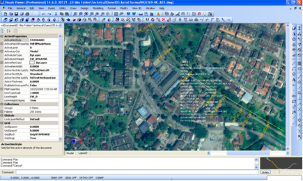
The Aerial photographs are used in HEADS Site for drawing the alignment by considering the Land use
Page 13 off 24
Site Leveling And Grading
For any site development the Leveling Grading of the site is the job next to land acquisition and planning for excavation platforms at various elevations and maintaining desired slopes in 3 dimensional perspectives. The estimation of earthwork in cut & fill is computed accurately by software HEADS Site in well formatted Tabular format following Stations defined along the reference Line. Along with the Digital Terrain Model (DTM) it generates Contours, Elevations on Grids, 3D Surface etc. and all as CAD Drawings. The built-in CAD engine is highly powerful with complete drafting and editing facilities. The drawings are compatible to AutoCAD and all other popular CAD softwares.
Land Acquisition and Land Record Maintenance HEADS Site - Infra features for in MS-Access database systems having MS-Excel compatibility. The land records are linked with respective land drawings to share various details of land records in text tables and land drawings. All the drawings are compatible to AutoCAD and other popular CAD softwares. Land records may be retrieved in various specified formats from database or drawings. The relationship between the land map drawings and related records in database management system is highly useful for land record maintenance.
Page 14 off 24
Detail Engineering Design of
Horizontal Alignment,
Vertical Profile,
Cross Section, and
Coach Profile in Railway Tunnels
Structural Analysis and Design of
Tunnel Portal, and
Tunnel Lining
Page 15 off 24
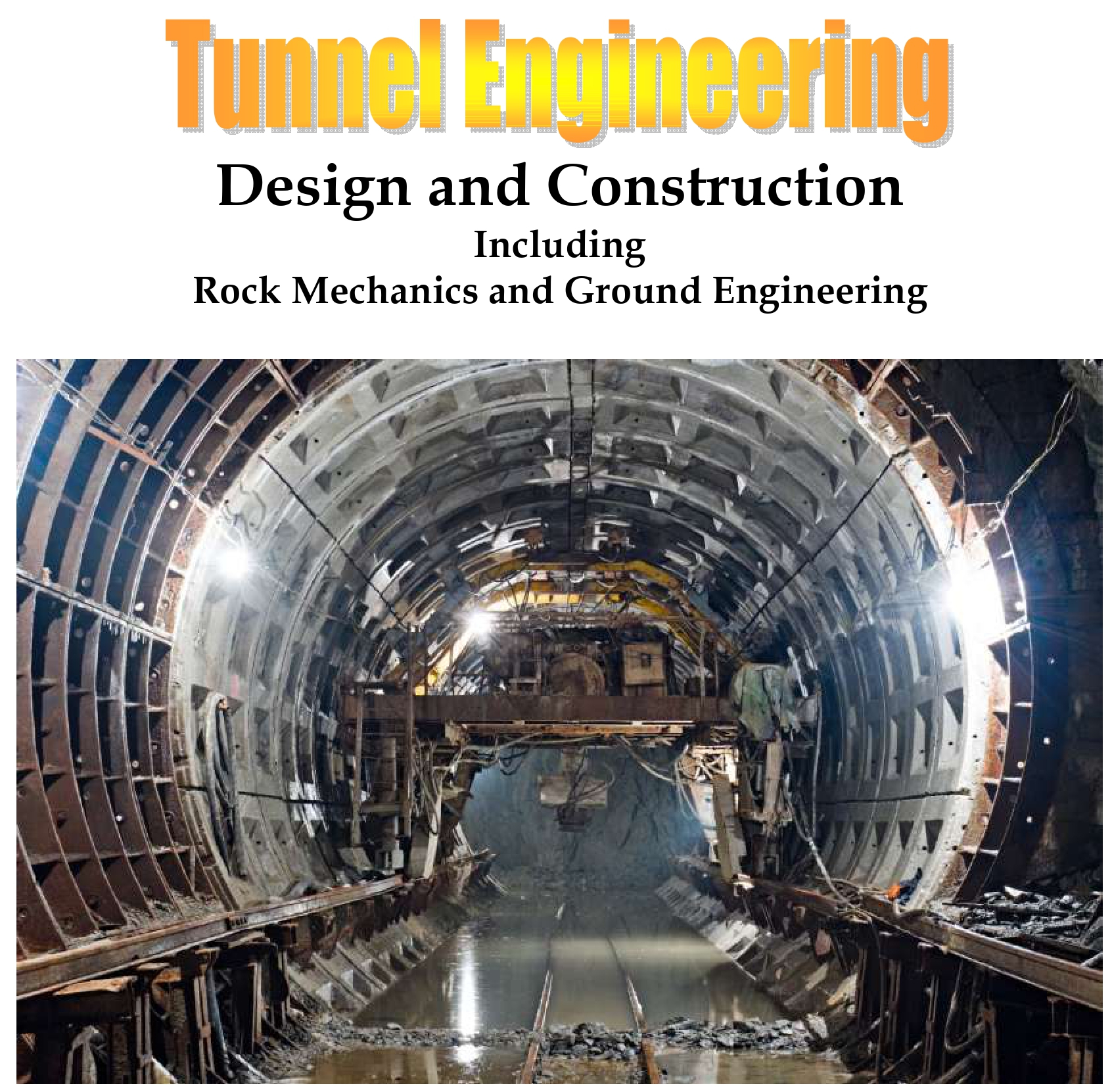
INTRODUCTION:
Tunnel Planning and Design with Overview of the Region shall be done by using software ASTRA Pro as described below
Tunnels are sometimes inevitable in urban as well as non-urban situations for various reasons. In this example we are going to design a tunnel of length 200 metres in urban location where at-grade and elevated highways already exist and to improve the ‘Level Of Service’ (say from ‘C’ to ‘B’) a tunnel at the intersection is the appropriate solution. On either side of the underground tunnel the approaches will be required, but not taken up here. In case of constraints for ‘Cut & Cover’ we chose NATM (New Austrian Tunnelling Method) Tunnel.
The aerial view of the region may be obtained by digitizing a satellite view by Google image, in true co-ordinates and the alignment of tunnel on ground surface may be designed in HEADS Site on the drawing thus created. We shall do the design of alignment by using the total station survey data on the surface.
Page 16 off 24
Tunnelling is unique when compared to other types of civil construction. In non-tunnel projects like a large building or treatment plant there are usually many places to work at the same time, so the work can continue even if there is a problem holding up work at one location. Tunnels are long linear undertakings with few opportunities to perform the work at more than one location. Tunnels are also a series of repetitive operations each of which usually must be finished before the next can be started. This uniqueness and the linear, repetitive nature of the work must be understood by the planners and builders of tunnel projects to control and manage the project to a successful conclusion.
Perhaps the most significant factor impacting tunnel cost and schedule is the type of geologic material that the tunnel will be mined through and the amount of ground and surface water that will be encountered or crossed. Tunnels are mined through rock, soil or a combination of both. The geology encountered determines the tunnelling methods that will be used, the speed that the tunnel can be constructed and the types of specialized equipment that are required.
Planning for a road tunnel requires multi-disciplinary involvement and assessments, and should generally adopt the same standards as for surface roads and bridge options, with some exceptions. Certain considerations, such as lighting, ventilation, life safety, operation and maintenance, etc. should be addressed specifically for tunnels. In addition to the capital construction cost, a life cycle cost analysis should be performed taking into account the life expectancy of a tunnel. It should be noted that the life expectancies of tunnels are significantly longer than those of other facilities such as bridges or roads. Traditionally, tunnels are designed for a life of 100 to 125 years. However, existing old tunnels (over 100 years old) still operate successfully throughout the world. Recent trends have been to design tunnels for 150 years life.
There are three main shapes of highway tunnels - circular, rectangular, and horseshoe or curvilinear. The shape of the tunnel is largely dependent on the method used to construct the tunnel and on the ground conditions.
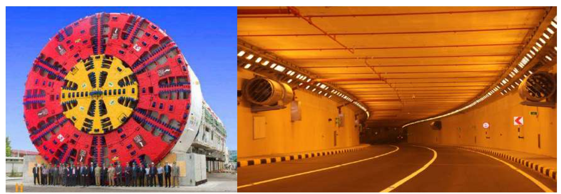
Rock reinforcement for initial support includes the use of rock bolts with internal metal straps and mine ties, un-tensioned steel dowels, or tensioned steel bolts. To prevent small fragments of rock from spalling, wire mesh, shotcrete, or a thin concrete lining may be used. Shotcrete, or sprayed concrete, is often used as initial lining prior to installation of a final lining, or as a local solution to instabilities in a rock tunnel. Shotcrete can also be used as a final lining. It is typically placed in layers with welded wire fabric and/or with steel fibres as reinforcement. The inside surface can be finished smooth and often without the fibres. Precast segmental lining is primarily used in conjunction with a Tunnel boring machine (TBM) in soft ground and sometimes in rock.
The size and type of vehicles to be considered depend upon the class of road. Generally, the tunnel geometrical configuration should accommodate all potential vehicles that use the roads leading to the tunnel including over-height vehicles such as military vehicles if needed. Road tunnels should have at least the same traffic capacity as that of surface roads. However, traffic will slow down if the lane width is less than standards (too narrow) and will shy away from tunnel walls if insufficient lateral clearance is provided inside the tunnel.
Tunnels as any other structures are affected by different loads and stresses. Generally, the loads on tunnels consist of both static and dynamic loads. These loads must both be considered in the tunnel design process. In process design, the stability of tunnels and other underground structures under the influence of seismic waves and dynamic load is one of the important issues that should be studied carefully. Although seismic waves are not the only cause of earthquakes, however, earthquakes are the most known source of seismic waves. In addition, the movement of trains in underground tunnels, the operation of machinery on ground surface and many other activities as such produce seismic waves that if to be neglected. Such damages not only result in an increase in costs, but also remain to be a source of danger to the human lives. At Page 16 of 239 Underground Structures Stress, Strain, Stability & Support of Tunnel are collected from various real projects.
Page 17 off 24
Analytical methods are very useful in geo-mechanics because they provide results with very limited effort and highlight the most important variables that determine the solution of a problem. Analytical solutions, however, have often a limited application since they must be used within the range of assumptions made for their development. Such assumptions usually include elastic behaviour, homogeneous, isotropic material, time independent behaviour, quasi-static loading, etc. Geo-materials such as soils and rock masses display non-linear behaviour, either because this is inherent to the material or because it has been externally induced. Rocks and soils may not be isotropic or homogeneous, and the loading may not be static, or the geometry of the problem may be complex. In these cases, solutions can only be obtained numerically.
Numerical methods have been extensively used in the past several decades due to advances in computing power. In a broad sense, numerical methods can be classified into continuum and discontinuum methods. Continuum methods may incorporate the discontinuities in the medium, if present, explicit or implicitly, while in discontinuum methods, discontinuities are incorporated explicitly. The need to use, for a particular problem, continuum or discontinuum methods depends on the size, or scale, of the discontinuities with respect to the size, or scale, of the problem that needs to be solved. There are quite a large number of numerical methods that have been used in the literature to estimate the behaviour of geo-materials. The most important or at least the most used methods are: Continuum, Finite Difference Method (FDM), Finite Element Method (FEM) and Boundary Element Method (BEM); Discontinuum, Distinct Element Method (DEM), Discontinuous Deformation Analysis (DDA), and Bonded Particle Model (BPM). [Antonio Bobet].
General Description of Various Tunnel Types
The selection of a tunnel type depends on the geometrical configurations, the ground conditions, the type of crossing, and environmental requirements. For example, an immersed tunnel may be most suitable for crossing a water body; however, environmental and regulatory requirements might make this method very expensive or infeasible. Therefore, it is important to perform the tunnel type study as early as possible in the planning process and select the most suitable tunnel type for the particular project requirements.
The principal types and methods of tunnel construction that are in use are:
Page 18 off 24
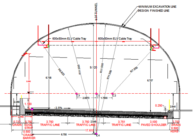
HEADS Site features for the Design of Highway Tunnels alignment, profile and cross sections with Quantities separately for Design cut, Over cut, Under cut and As Built cut. Structural design of Tunnel Lining for Ribs, Portals and Tunnel are most important facilities in this software system. HEADS Site features for CAD based checking of Coach Profile inside the Tunnel. All the design work produce construction drawings in CAD,
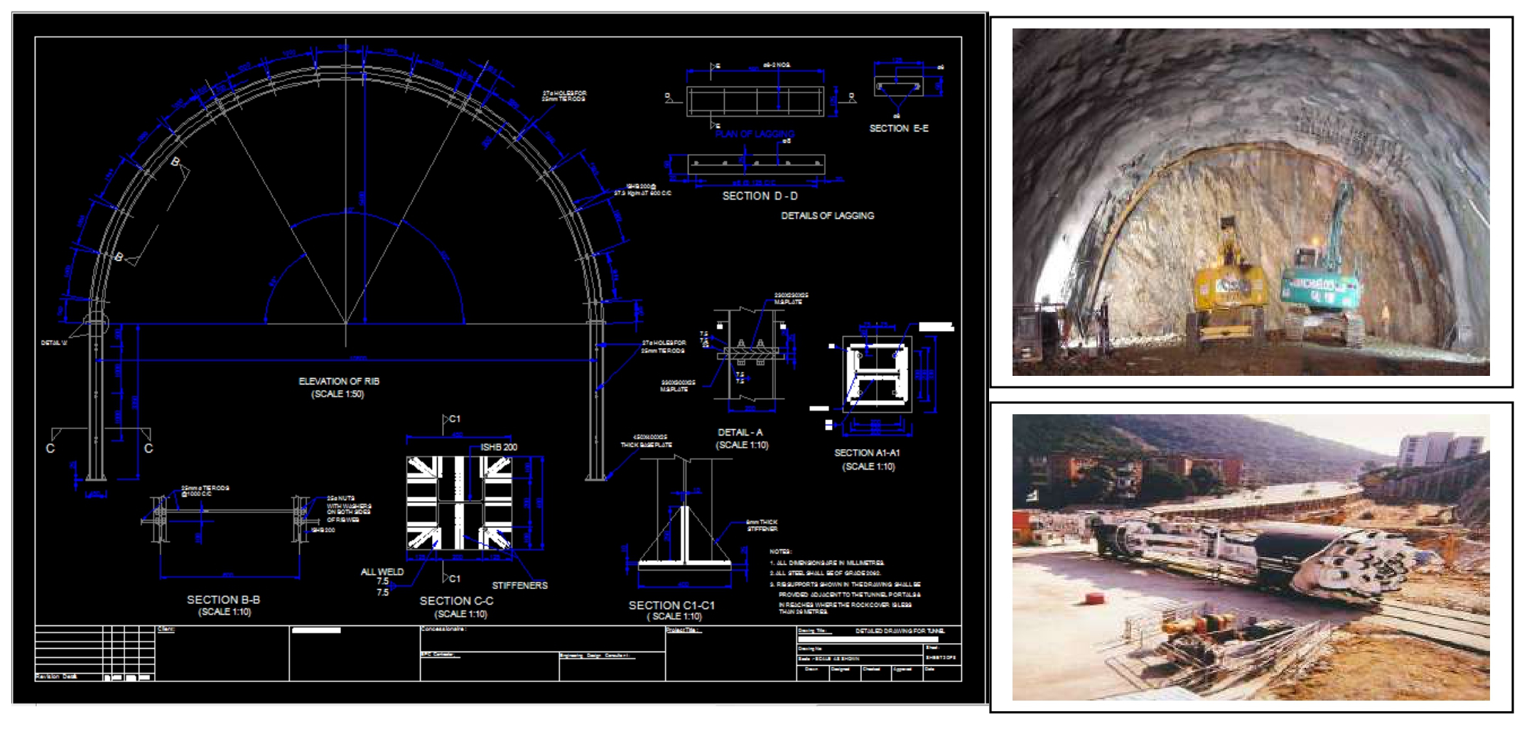
The Boring Cut Quantities are estimated for Design Cut, As Built Cut, Over Cut and Under Cut. The “Pay Line” outside the design section is also defined to include the desired amount of overcut in the measurements. Ready to Plot and Editable CAD Drawings are created as the output.

Page 19 off 24
HEADS Site - Infra features for Tunnel Design
Tunnels are constructed to create travel routes without disturbing the existing roads & structures on the surface and environment, ensure uninterrupted traffic flow, shorter travel distance and shorter travel time. Tunnels are mainly of two categories Cut & Cover and Bored Tunnels.
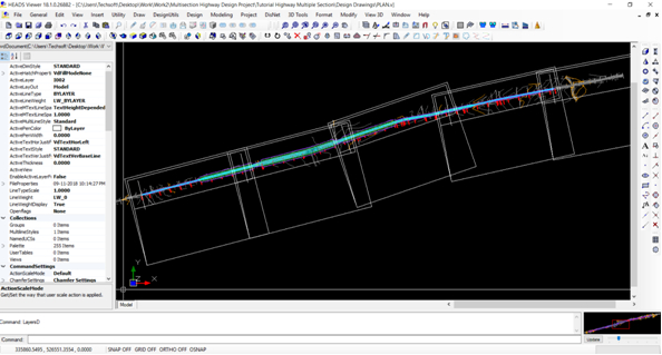
Bored Tunnels are commonly constructed for highway or railway or hydel power projects. These are underground structures, here the construction depends of accurate monitoring, which is done by Robotic Total Stations which automatically records scanned data as soon as some segment is constructed. HEADS Site processes the scanned data to create CAD drawings and related report to describe section wise design cut, Over cut, Under cut to monitor the construction with best possible accuracy.
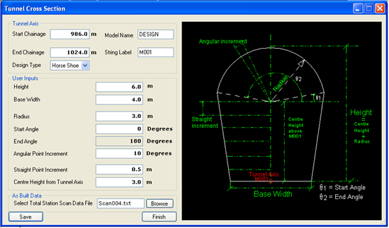
Inside metro tunnels the rail coaches are tilted at curved sections, here HEADS Site generates complete set of CAD drawings for coach profiles at desired interval, at curves. This enables the users to check the lateral clearance available between the tilted coaches and the side walls of the tunnel. CAD based design for Horse Shoe/Semi Circular/Circular/Rectangular/Custom type Tunnel Sections
Page 20 off 24
The Boring Cut Quantities are estimated for Design Cut, As Built Cut, Over Cut and Under Cut. The “Pay Line” outside the design section is also defined to include the desired amount of overcut in the measurements. Ready to Plot and Editable CAD Drawings are created as the output.
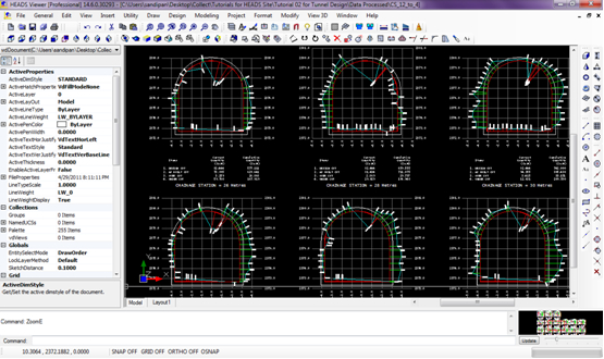
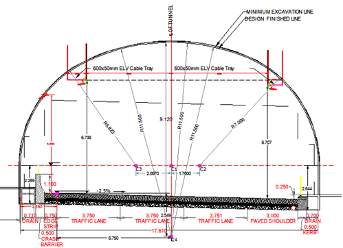
The Geometric design of Tunnel features for Horizontal Alignment, Vertical Profile and Customized Cross Sections by using Scan Survey Data by Robot Total Station along with Estimation of Excavated Quantities for Design cross sections, As-built cross sections in respect of Pay-cut and studies on Coach profile.
The Structural design of Tunnel is based on RMR Increments for Rock Bolting, Shotcrete, Steel Ribs, Wire Mesh, RCC Lining and Tunnel Portals.
Page 21 off 24
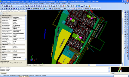
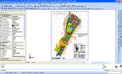
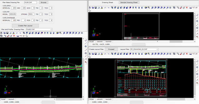
For highway of length 100 or 200 km it is indeed tedious to layout sheets for every 1 km length, on full length PLAN drawing, to cut the full length drawing into 1 km pieces, as required to produce the PLAN-PROFILE drawings. The same is now automatic for user selected sheet size, scale, start and end chainage, length in each sheet, etc. This is now saving significant time to create a large number of PLAN drawings containing desired length of the road.
Upon finalizing the project drawing sheet by editing the sample drawing sheet, the cutting of PLAN drawing of full length into pieces of desired length and finally the insertion of PLAN and PROFILE parts of every kilometer of road is now just a mouse click only. The intelligence in HEADS Site is the best in the industry for its power and accuracy.
Search in YOUTUBE for “Techsoft Forum”, and go to ‘Play List’ to watch the videos ….
Page 22 off 24
HEADS Site is widely used by various Govt. Departments and Private Sector Consultants.

HEADS Site - Infra
Each package contains the following items:
Page 23 off 24

(An ISO 9001:2015 Company)
Mobile/Whatsapp: +91 9331 9330 39
Tel: +91 33 4008 3349, +91 33 4603 6129
Website: www.techsoftglobal.com
Email: techsoftinfra@gmail.com, techsoft@consultant.com
Page 24 off 24
 Previous