
The most powerful and largest software System for Highway Engineering and Design with special features for Uniform & Multi Section Highway Widening & Strengthening, Hill Roads, Low Cost Rural Roads, Tunnels Geometric Design, Pavement Design / Rehabilitation, Profile Correction, Grade Separated Interchanges, At-Grade Intersections with Type Selection & Design, Swept Path Analysis, Car Racing Track Design, Bituminous / Asphalt Mix Design, Highway and Hill Road Drainage Design, Highway Lighting Design, CAD Construction Drawings, Bill of Quantities etc.
[Operating Systems: Microsoft Windows 7/Win8 with 32 / 64 Bit, Minimum 2 GB RAM, 100 GB HDD space]

In Highway Engineering various software products are available in the market, but the uniqueness of HEADS Pro lies in its simplicity for applications, such as multiple section Highways are designed for varying configuration in cross sections in one go, Automatic AI-based production of Design/Construction drawings which saves the drafting time considerably, Safety check for visibility with 3D Drive Through at different speeds, enabling GPS based constructions etc. HEADS Pro has its own powerful CAD engine making drawings compatible to AutoCAD and is best appreciated for its Features, Completeness, Versatility, Fast Processing, Simplicity, Formatted detail report.
Cloud based Process / Storage / sharing facilities are available as optional. On procuring multiple licenses, say, four licenses, and installing at four different locations anywhere in the country/world, the project name, user name and password may be shared with those four license locations. They all can access cloud server to view the design and drawings, modify, re-process, download, upload the work at the cloud storage "Techsoft Drive".
Website: www.techsoftglobal.com
Email: techsoftinfra@gmail.com, techsoft@consultant.com
Mobile: +91 9331 9330 39
Tel: +91 33 4008 3349, +91 33 4603 6129
Page 1 off 36
HEADS Pro Highway Design is presented by 3D Drive Through by UC-win/Road
Web link: https://youtu.be/2mAyBM8MYB8


HEADS Pro enables the GPS based Motor Graders and Dozers for faster and accurate construction by eliminating a series of survey checks for level verifications (Refer to page 32).
Page 2 off 36
HEADS Pro is a CAD based String modeling software and features for the followings:
Applications for Projects :
Applications for Engineering Design :
Special Points on Technical Specifications:
Page 3 off 36
Topographical Survey or Satellite Data Processing
Computer applications are very effectively helpful in every stage of Highway development projects starting from Conceptual phase to Preliminary design, to Detail engineering to Construction. The collecting and processing of ground survey data is the first step in computer aided highway design. The process includes creating of ground model, Digital mapping to create the survey base plan, triangulation to create the Digital Terrain Model or DTM and thus the ground Contours and finally the ground long and cross sections.
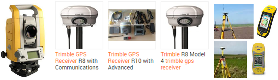
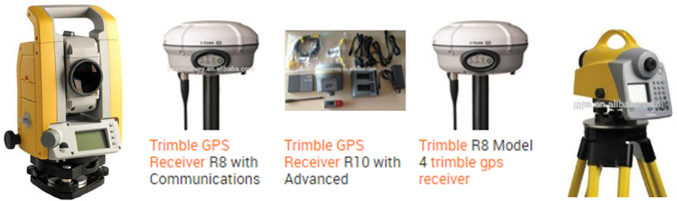
The collecting of ground data uses either obtaining the field survey data most commonly by using the Total Station instrument or obtaining the ground elevation data with the latest available satellite based technology which also helps in identifying the best possible route of the road, its realignment and the widening scheme.

The Survey data whether by Total Station survey or by Satellite data, but the data must be made available in the desired format of five columns for: Serial Number, Easting (metres), Northing (metres), Elevation (metres) and Feature Code and saved as a text file (for example SURVEY.TXT) which can be opened in 'Notepad'. In its has five columns of data, when a data record with Serial No. '0' is met then it discontinues the last feature and reads a new feature in the Ground Model. After creating the ground model it is drawn to create the survey base map and is described in the relevant section of this book.
The model Name, String Label and increments for primary, secondary and Text are set with default names & values. If the ground is of flat nature then user has to reduce the primary contour increment as 0.5 or 0.1 to get contours for the relatively flat ground. The secondary contour increment is always five times of increment of the primary contours. Texts for contour elevations are displayed on the secondary contours.
The various Tutorial Videos are available to understand and master the above processes by watching the Tutorial Videos and next by operating software HEADS Pro by following the steps as described in the HEADS Pro Design Manual.
Page 4 off 36
Processing of Topographic Survey Data by Total Station instrument
The project corridor may be identified by site reconnaissance survey and by using Topographic maps along with satellite imageries by using Google Earth, as well.
The ground elevation data may be either obtained by Total Station Survey or by downloading from SRTM (Shuttle Radar Topography Mission) by using internet. User may procure the computer program Global Mapper to download ground topography data from internet. Most widely the softwares use Total Station Survey Data for processing Topographical details most effectively and economically in various highway construction projects.
The next job is to prepare the Survey Base Plan or Ground Model from the ground survey data with Total Station. By selecting drawing feature symbols from CAD Block library, the various texts obtained from the surveyors are also placed correctly in the Base Plan drawing. The drawing is made in CAD layered system and is compatible to AutoCAD and other popular CAD softwares.
Finally the Digital Terrain Model (DTM) is created by using the Total Station survey data by Triangulation and subsequently processed for contouring.
Processing of Cross Section Survey Data by Auto / Digital Level instrument
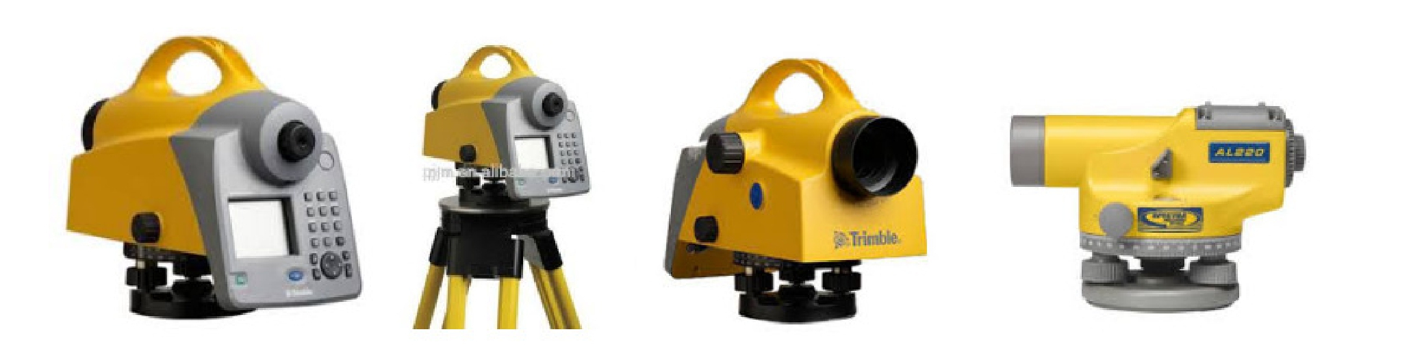
The Autolevel data contains Chainages at a regular / constant interval, the distances on the cross section on either side of the centre point 0.0, left side in '-ve' & right side is '+ve' and the elevations (Z) at all distances on either side of the centre point. The data do not have Easting (X) and Northing (Y) at these points where (Z) is available. So, to get Easting (X) and Northing (Y) at these points an alignment is to be defined, which passes through the centre point at '0.0' of the cross sections at every chainage. The alignment must have the chainages at intervals same as that in the Autolevel Cross section survey. Referring to this alignment the program will obtain the X & Y Coordinates of each point on the cross section, this helps in making Triangulation, Digital Terrain Model and finally the Contours of the ground. Only the survey base plan drawing by digital mapping will not be created from ground model, which needs Total Station data for reading various features like Houses, Drains, Electric Poles, Boundary walls etc. on the ground.
Page 5 off 36
Processing of Bearing Line Survey Data
The Bearing Line method of survey is very widely used in the design of hill roads. Every hill road commonly has hill on one side and valley on the other side. In Bearing Line Survey the traverse passes through the foothill side, which changes its side with respect to the road to stick to the hill.
Ground Modeling
The data in the Total Station survey data file must be made available in the following format and saved as a text file (for example SURVEY.TXT) which can be opened in 'Notepad'. It has five columns of data, when a data record with Serial No. '0' is met (as after Serial No. 5) then it discontinues the last feature and reads a new feature (from Serial No. 1) in the Ground Model.

HEADS Pro may be used for Safety Studies for High Speed Expressways. For the design of railways at design speed 120 KPH or more by following relevant International Standard, HEADS Pro Rail is the most appropriate road design software HEADS Pro creates 3 dimensional perspective view of the terrain and the designed railway. It can convert the design output in LandXML format and supports Visualization and Drive Through by UC-win/Road.
HEADS Pro in project cost estimation by Analysis of Item Rates. With In built formulas on components of Materials, Equipment and Laborer the Unit Item Rates are computed for the Earthwork for Embankment, Pavement, Culvert, Bridge and other work in worksheet format.
Page 6 off 36
Processing of downloaded Ground Elevation Data from Satellite by internet
By defining tentative alignment by drawing straights by “My Path” in Google Earth to define the project corridor and subsequently downloading ground elevation data by using Global Mapper minimizes the exercise to transform the Surveyors coordinates in TM (Transverse Mercator) into Global Coordinates in UTM (Universal Transverse Mercator) / GPS. The alignment file may be saved as KML/KMZ file. This file may be opened in future in Google Earth to mark various features along the corridor, for example, the road alignment with existing ‘Land-use’ etc. The area may also be identified or verified by site reconnaissance survey or by using Topographic maps or by procuring satellite imageries from the survey department.
Next, the KML/KMZ file may be opened with Global Mapper and saved as DXF file. Also, the ground elevation data may be downloaded with Global Mapper from SRTM (Shuttle Radar Topography Mission). The DXF file of the alignment is opened in HEADS Viewer and the alignment geometrics are design as Horizontal Alignment of the project highway.
The downloaded ground elevation data is to be opened with software MS-Excel for saving in the desired format. Next the ground data is opened with software HEADS Pro to create the ground model, and next the Digital Terrain Model along with contours are to be generated for the entire area under the study. This enables the engineers to Develop the Survey Base Plan, Digital Terrain Model (DTM) by Delauny Triangulation, Ground Contours at user given primary & secondary intervals, 3D Surface with rendering, Ground Long and Cross Sections. The Digital mapping facility by drawing ground model enables the users to prepare Survey base Plan drawings over Google Pictures using the CAD engine of software HEADS Pro.

The contour are superimposed on the satellite imagery
The ground survey work also includes obtaining of Traverse coordinates with closing error correction by Bowditch, Transit & Close Link methods, EDM Survey, Coordinate Transformation from WGS84 to Lambert Conformal Conic Projection (Long Lat to East North) and the reverse with Spheroid Everest 1956. This enables to install Survey reference pillars along the proposed highway route for their reference during the construction.
Software HEADS Pro will be applied for the design of highway widening with reference to an existing road with multiple cross sections and multiple alignments, where the road cross sections may change with different configuration and with the change in widening pattern from Left to right to concentric along the route from origin to destination. The design has special treatment in hill stretches. Provision for tunnels is also possible with very special design techniques.
Page 7 off 36
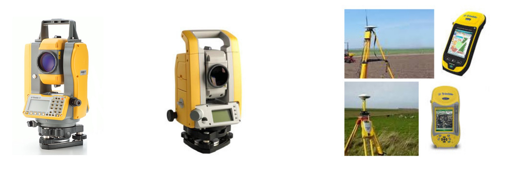
Processing of TRIMBLE Robot Total Station Scan Laser Survey Data

The TRIMBLE Robot Total Station survey data is very widely used in the construction of Bored Tunnels. This is to be noted that the survey is carried out after the boring is done for the tunnel, by following the design horizontal alignment, vertical profile and proposed cross section for the tunnel. The survey data is used to estimate the actual boring against the design cross section of the tunnel. At every chainage the As-Biult and Design Cross Sections are plotted. From the cross sections the ‘Under Cut’ and ‘Over Cut’ quantities are computed by comparing the as-built against the design cross section. Some times in case of excessive overcut the cut quantity is considered up to certain extent outside the design cross section, which is marked as the ‘Pay Line’. Proper measures are to be taken to restore all the over cuts and to remove unwanted soil/rock at the under cuts to match the bored cross sections with the design cross section. All these actions can be done by using the Robotic Total Station survey data and thus processing by HEADS Pro to generate cross sections and quantities for Design Cut, As-built Cut (Under Cut & Over Cut) and the Pay Line, also by creating CAD drawings and detail report.

Page 8 off 36
Processing of Traverse Survey Data
HEADS Pro generates Traverse Report describing corrected Traverse and its coordinates with closing error corrections by Bowditch, Transit and Closed link, with EDM applications.

The HEADS Pro CAD view of drawing with uncorrected and corrected Traverse and its coordinates.

Page 9 off 36
Processing of Drawing File in 3D to extract ground data
The survey plan drawing is made in 3 Dimension and the processing is done to extract the Layer wise x,y,z data of various features of the drawing. The data is saved as Text data in Total Station format and created model with string labels taking from the layer names by saving in the model files.

Triangulation and Contours
The model Name, String Label and increments for primary, secondary and Text are set with default names & values. If the ground is of flat nature then user has to reduce the primary contour increment as 0.5 or 0.1 to get contours for the relatively flat ground. The secondary contour increment is always five times of increment of the primary contours. Texts for contour elevations are displayed on the secondary contours.

Page 10 off 36
PROCESSING OF DOWNLOADED GROUND ELEVATION DATA
HEADS Pro minimizes the exercise to transform the Surveyors coordinates into Global UTM / GPS Coordinates using in-built CAD engine, next the transformed drawing may be opened for conversion to KML/KMZ file to open in Google Earth to define the road alignment for Site Layout, Green Field alignments, Bypasses and Realignments as larger area with existing Land use are visible. The area as identified by site reconnaissance survey, by using Topographic maps and satellite imageries. Next, the ground elevation data may be downloaded from SRTM (Shuttle Radar Topography Mission) and Digital Terrain Model along with contours may be generated for the entire area under the study. This enables the engineers to Develop the Ground Model, Digital Terrain Model (DTM) by Delauny Triangulation, Ground Contours, Ground Sections at user given primary & secondary intervals, 3D Surface with rendering, Ground Long and Cross Sections, Digital Mapping and BoQ. The Digital mapping facility enables the users to prepare Survey base Plan drawings over Google Pictures using the CAD engine of HEADS Pro.
HEADS Pro features for Traverse coordinates with closing error correction by Bowditch, Transit & Close Link methods, EDM Survey, Coordinate Transformation from WGS84 to Lambert Conformal Conic Projection (Long Lat to East North) and the reverse with Spheroid Everest 1956. This enables to install Survey reference pillars along the proposed highway route for their reference during the construction. Satellite images and Aerial Photos for producing the best possible design.

The Aerial photographs may be used for drawing the alignment by considering the Land use
The design is created as 3-Dimensional model and is powerful for design of highways with multiple cross sections and multiple alignments, where the road cross sections may change with different configuration and with the change in widening pattern from Left to right to concentric along the route from origin to destination. The design has special treatment in hill stretches. for presentation purposes.

Page 11 off 36
LAND RECORD MANAGEMENT SYSTEM
Relational Data Base Management System (RDBMS) by Microsoft Access is used in association with Microsoft Excel and HEADS Pro CAD Viewer
For any site development project for Township, Industrial Plants, Roads, Airports, Housing projects the Acquisition of Land for the site is the next job for preparing for construction. The list of names of the land owners, Land category, Land Plot ID, Plot Number, reference District and State in the country. The owners of the acquired land plots are paid by the project authorities. A proper storage of the details along with land maps are therefore essential for the project. The record details are maintained in Relational Data Base Management Systems (RDBMS) and all the land maps as CAD Drawings. The built-in CAD engine is highly powerful with complete drafting and editing facilities. The drawings are compatible to AutoCAD and all other popular CAD softwares.

Land records may be Entered and stored in MS Access Database format and CAD Drawings
For any Site preparation the land records and land maps in the existing ground are most essential and properly coordinated by HEADS Pro. The establishment of correlation between the database records and the related drawings are extremely useful facilities for maintaining the land records by the users.

Page 12 off 36
Land records may be retrieved in various specified formats from database or drawings. The relationship between the land map drawings and related records in database management system is highly useful for land record maintenance.

Road Safety on Night Time Visibility - Street Lighting Illumination Design
A section of the roadway may be selected for measurement of illumination and to study the illumination pattern. An area of 44.5 metres x 25.5 metres on the roadway may be selected. Here the distance between two consecutive light posts is 44.5 metres and it is measured as the length along the travel direction of the road. The width of the roadway illuminated by the street lights is 25.5 metres. The height of light posts may be 12 metres. The illumination by reflected light from the surface of the road at every grid point at an interval of 0.5 metre may be measured by illumination meter and recorded in a raw data file along the length and width of the area under the study. The data in the raw data file are to be processed by triangulation and illumination contours. The Type of Lamp (Murcury/Sodium/Halogen/LED), power of Lamp, Height of Lamp and Spacing of Lamp Posts may be adjusted to get the required illumination pattern.

Page 13 off 36
Design of Highways & Expressways is aided by applying different configuration for Typical Cross Section (TCS) from various chainage to chainage to chainage along its alignment starting from origin to destination.
The cross section of Dual carriageway configuration for 4/6/8 Lane highway or expressway in Non-urban locations may be selected with necessary modifications from various applicable cross sections

The cross section of Dual carriageway configuration for 4/6/8 Lane highway or expressway with service roads on either side in Non-urban locations may be selected with necessary modifications

Page 14 off 36
The cross section of Dual carriageway configuration for 4/6/8 Lane highway or expressway with service roads on either side in Urban locations may be selected with necessary modifications

The cross section for flyovers / underpasses with dual carriageway configuration for 2/4/6/8 Lane highway or expressway with service roads on either side in either urban or non-urban locations may be selected with necessary modifications

Page 15 off 36
The cross section with single carriageway configuration for highway or expressway in non-urban locations may be selected with necessary modifications

The widening pattern may be defined as Left / Concentric / Right / Flyover from chainage to chainage with necessary modifications

Page 16 off 36
Built-in CAD Engine For Interactive Design and Drawings
HEADS Pro features for its various options available for the geometric design of road alignment either by Interactive design over the survey plan drawing or by Automatic wizard or by Processing alignment data or on Satellite imagery.

HEADS Pro features for its various options available for the geometric design of road profile either by Interactive design over the ground long section or by Automatic wizard with optimization or by Processing vertical profile data.

Page 17 off 36
Design of At-grade intersections and Roundabouts with built-in CAD enable the users to handle any complex site situation for in best possible way.

HEADS Pro has built-in CAD enable the users to handle any complex site situation for design of at grade intersections acceleration lane, deceleration lane, merging lane, diverging lane in best possible way.

Page 18 off 36
Design of multi level Grade Separated Interchanges with design of alignment, vertical profile and cross sections for main lines, each loops, slip roads, merging lanes and diverging lanes.

HEADS Pro features for CAD based design where the verification of the work done can be done instantaneously before going to the next step, By providing special facilities user can design Road with Uniform Cross Section, Multiple Cross Sections, Highway Widening and Changing of widening pattern either as concentric or on Left or Right side By applying different Typical Cross Sections from Chainage to Chainage.

Page 19 off 36
Design of Low Cost Rural Roads is available by selecting from Core Network of Village Roads, identifying the origin to destination of each road by using GPS, developing alignment geometrics, pavement design, BoQ and Cost estimation and finally producing the construction drawings helps in preparing the Bid documents and further for construction at site.

HEADS Pro reduces the time for project preparation significantly by using various latest technologies like GPS, Satellite imagery to complete the Detail Project Report (DPR) in the shortest time. In the design of pavements the use of Optimization Technology keeps the earthwork to the desired level only with respect to the HFL and avoiding the undesired quantity of earthwork to minimum possible extent.

Construction of Low Cost Rural Roads may be either for new roads or for resurfacing of the existing roads with various pavement layers which designed for various rural commodity transport vehicles, Agricultural Tractors and must be strong enough to last long.

Cross section Drawing for new single carriageway construction
Page 20 off 36
Design of Hill Roads is available with special treatments for (i) Carriageway Widening at curves (ii) Provision for slopes on cut side varying with the depth, (iii) Provision for Gabion Walls on cut side and (iv) provision for Retaining Walls on the fill / valley side.

Widening of Hill Roads using Varying Slopes on Cut side depending on Depth and using Gabion Wall on Cut side and Retaining wall on Fill / Valley side is best designed.

Provisions for Extra Widening following the country’s design standard is important in the design of Hill Roads which is not available in the market available softwares, so the designer must be careful in selecting the right software product to keep provisions of inside / outside / both sides widening at the curves.

Page 21 off 36
Tunnel Geometrics HEADS Pro features for the Design of alignment, profile and cross sections with Quantities separately for Design-cut, Over-cut, Under-cut and As-Built cut for Highway Tunnels. HEADS Pro features for CAD based checking of Coach Profile inside the Tunnel. All the design work produce construction drawings in CAD,

The Boring Cut Quantities are estimated for Design Cut, As Built Cut, Over Cut and Under Cut. The "Pay Line" outside the design section is also defined to include the desired amount of overcut in the measurements. Ready to Plot and Editable CAD Drawings are created as the output.

Page 22 off 36
Planning for a road tunnel
Planning for a road tunnel requires multi-disciplinary involvement and assessments, and should generally adopt the same standards as for surface roads and bridge options, with some exceptions. Certain considerations, such as lighting, ventilation, life safety, operation and maintenance, etc. should be addressed specifically for tunnels. In addition to the capital construction cost, a life cycle cost analysis should be performed taking into account the life expectancy of a tunnel. It should be noted that the life expectancies of tunnels are significantly longer than those of other facilities such as roads and bridges. Traditionally, tunnels are designed for a life of 100 to 125 years. However, existing old tunnels (over 100 years old) still operate successfully throughout the world. Recent trends have been to design tunnels for 150 years life.
The size and type of vehicles to be considered depend upon the class of road. Generally, the tunnel geometrical configuration should accommodate all potential vehicles that use the roads leading to the tunnel including over-height vehicles such as military vehicles if needed. Road tunnels should have at least the same traffic capacity as that of surface roads. However, traffic will slow down if the lane width is less than standards (too narrow) and will shy away from tunnel walls if insufficient lateral clearance is provided inside the tunnel.
The commonly used tunneling are (i) Cut-and-cover tunnels, (ii) Bored or mined tunnels, (iii) Rock tunnels, (iv) Soft ground tunnels, (v) Immersed tunnels, (vi) Jacked box tunnels.
The structural design of tunnels is available in our software ASTRA Pro, mainly by Drill & Blast / New Austrian Tunneling Method (NATM). Design of Tunnel Support System is done with Rock bolts, Lattice girder steel ribs, Wire mesh or Fiber Reinforced Shotcrete, based on geological mapping with RMR. Design of RCC Tunnel Portal and Tunnel lining are done by Finite Element Model Analysis.
Analysis for Stability of Slopes
Slope stability analysis is performed to assess the safe design of a human-made or natural slopes (e.g. embankments of dam, dyke, road, cuts, open-pit mining, excavations, landfills etc.) and the equilibrium conditions. Slope stability is the resistance of inclined surface to failure by sliding or collapsing. The main objectives of slope stability analysis are finding endangered areas, investigation of potential failure mechanisms, determination of the slope sensitivity to different triggering mechanisms, designing of optimal slopes with regard to safety, reliability and economics, designing possible remedial measures, e.g. barriers and stabilization.
Successful design of the slope requires geological information and site characteristics, e.g. properties of soil/rock mass, slope geometry, groundwater conditions, alternation of materials by faulting, joint or discontinuity systems, movements and tension in joints, earthquake activity etc. The presence of water has a detrimental effect on slope stability. Water pressure acting in the pore spaces, fractures or other discontinuities in the materials that make up the pit slope will reduce the strength of those materials. Choice of correct analysis technique depends on both site conditions and the potential mode of failure, with careful consideration being given to the varying strengths, weaknesses and limitations inherent in each methodology.

Page 23 off 36
Highway Strengthening and Widening
In developing countries most of the projects are widening of the existing road carriageway. This needs strengthening of the existing carriageway with Profile correction followed by laying of Bituminous overlay at the top and on the other side there is construction of a new carriageway with full Pavement structure. This needs two separate designs for two carriageways in respect of Horizontal and Vertical alignment. In case the height of existing embankment is low then the surfaces of two carriageways will be at different levels. This is best done in HEADS Pro using the versatile String technique.

Split Carriageway Design for Road Widening

Split Carriageway section after Road Widening

Pavement construction for Road Widening
Page 24 off 36
Construction Drawings for Rehabilitation of Old Roads
Some times the existing single carriageway 2 lane road is proposed for rehabilitation after carrying out Benkelman Beam Deflection test and within the limited budgetary provisions. Here the central portion may be treated with Profile correction and a course of pavement overlay commonly by Bituminous Macadam or Dense Bituminous Macadam. In case the edges on both the sides are broken or damaged then full pavement structure for limited width may be proposed at the edges in such sections. HEADS Pro computes the quantities for Profile Correction Course (PCC), Overlay and for side layers with best possible accuracy and produces the drawings with various levels at specified distances. These drawings are most essentials for such construction.

Cross Section Drawing with Fly over and Service Roads for Highway Rehabilitation projects

Page 25 off 36
Construction and As-built Drawings are produced by HEADS Pro
HEADS Pro produces Plan-Profile and Cross section drawings for the projects in international standard, which means that the information mentioned in the drawing fulfills all construction requirements following the standards and specifications of most of the countries in the world.

Plan & Profile Drawing
HEADS Pro produces Survey Base Plan by Digital Mapping from the Ground Survey Text data and by selecting drawing feature symbols from CAD Block library, the various texts obtained from the surveyors are also placed correctly in the Base Plan drawing. The drawing is made in CAD layered system and is compatible to AutoCAD and other popular CAD softwares for any further editing/drafting. Contours and DTM, with Ground sections are also produced as Reports and CAD drawings for Plan & Profile, Cross sections. This saves the time significantly in preparation for the Detail Engineering Projects.

Survey Base Plan
Page 26 off 36
HEADS Pro features for Pavement Design in AASHTO and IRC methods for Flexible Pavement with stage construction facilities, Rigid Pavement by CRCP & JRCP, with Cumulative Fatigue Damage analysis, Pavement Overlay by Benkelman Beam Deflection test data, Design of Bituminous based on Marshall Test data for Bulk Density, Stability and Flow and Blended Grading of aggregates with diagram. Layered Pavement System Analysis is available to determine the increase in the strength of pavement using Geotextiles or Fiber Glass Geogrids / Geosynthetics. All the designs generate detailed illustrated design calculation report with relevant references to AASHTO Tables & Charts. The facility for computation of Equivalent Standard Axles in Millions (MSA) is also available with this system.

Design of Flexible Pavement in AASHTO method

Design of Rigid Pavement in AASHTO method
Page 27 off 36
Pavement Strengthening for Cracked / Distressed Pavements by Layered System Analysis
Reinforcing asphalt / bituminous layers by using Geogrids and reinforcing Subgrade by using Geotextiles
The cost of Pavement structure is important for every road project and compromising with the structure will not allow the pavement to last long. So the cost reduction is to be done without lowering its strength. Now products are available to incorporate the pavement to increase the strength and longevity at a lesser cost. This is commonly done by laying Geosynthetics layer in between the layers of Asphalt concrete and Dense Bituminous Macadam and also by laying Jute Geotextiles at the top of the Subgrade layer.
Geosynthetics are not decomposable but Jute Geotextiles are decomposable and both increase the life of pavement significantly. Jute Geotextiles are very useful when the road is to be constructed in unstable ground. It is available in plenty in India and Bangladesh and is an inexpensive material. If the ground is stable but traffic load is high then the pavement structure becomes expensive. To reduce the cost either less expensive layers or lesser thickness are to be thought of. In such case if the strength is to be maintained same as the original structure then incorporating of Geosynthetics is an effective solution.
This requires correct analysis to determine the strength of the pavement structure by using various layers of different strength and thicknesses. Every pavement option may also be studied with and without incorporating the Geosynthetics.
The strength of pavement is required by obtaining the Elastic modulus and Poisson’s ratio. The various companies are producing Falling weight Deflectometer, one of them is Dynatest (www.dynatest.com) and for analysis software HEADS Pro may be used for various options. In HEADS Pro software option is available for Analysis for Layered pavement System. It may be used for 2 or 3 or 4 layer Pavement system, where the Layers may be combined to define as a Bound (Asphalt/Bituminous) Layer, Unbound layer (Granular Base), Sub Base and Sub Grade. The input is required for Thickness of each Layer (excluding Subgrade), Modulus of Elasticity of each Layer and Poisson’s ration of each Layer (excluding Subgrade).

Page 28 off 36
The final result is produced as : Horizontal Strain, Vertical Stress and Vertical Deflection at the interface of each two Layers. The above results are improved by incorporating Geosynthetics or any other type of Reinforcement is used. The Analysis Report is generated with details of all Formulae and Calculation Steps and is highly useful for the users.

Analysis for Layered Pavement System

Analysis for Layered Pavement System…Result
Most effective for the repairing of Cracked Pavements
Page 29 off 36
Comparative study of results obtained from HEADS PRO

Laying of Geogrids are in progress

Geogrids Laid over cracked surface before laying the wearing course to strengthen the weakened asphalt course

Selection of Geogrids
A number of field tests are available to test the strength of the pavement at site after construction but it is very rare to find a facility to estimate the results before construction. So the procedure described above is expected to be highly useful to project authorities and consultants to decide on the pavement structure and the type of reinforcement to be used. This will ensure increased design life of pavement at a lesser cost.
Page 30 off 36
Multiple Layout of drawing sheet for automatic PLAN-PROFILE Drawings
For highway of length 100 or 200 km it is indeed tedious to layout sheets for every 1 km length, on full length PLAN drawing, to cut the full length drawing into 1 km pieces, as required to produce the PLAN-PROFILE drawings. The same is now automatic for user selected sheet size, scale, start and end chainage, length in each sheet, etc. This is now saving significant time to create a large number of PLAN drawings containing desired length of the road.

Upon finalizing the project drawing sheet by editing the sample drawing sheet, the cutting of PLAN drawing of full length into pieces of desired length and finally the insertion of PLAN and PROFILE parts of every kilometer of road is now just a mouse click only. The intelligence in HEADS Pro is the best in the industry for its power and accuracy.

Page 31 off 36
DESIGN OF HIGHWAY and Hill Road DRAINAGE
HEADS Pro has highly effective module for design of highway drainage, based on storm water duration and hydrological data and by using manning's coefficients the adequacy of the proposed drain section is checked.


The section of drain is considered based upon vertical profile of the highway and the location of discharge points. The design is difficult in plain terrain as the natural slope is not available so planning is to be done carefully.
Provision for adequate drainage is of paramount importance in road design and cannot be overemphasized. The presence of excess water or moisture within the roadway will adversely affect the engineering properties of the materials with which it was constructed. Cut or fill failures, road surface erosion, and weakened sub grades followed by a mass failure are all products of inadequate or poorly designed drainage. As has been stated previously, many drainage problems can be avoided in the location and design of the road: Drainage design is most appropriately included in alignment and gradient planning.
HEADS Pro enables the GPS based Moto Graders and Dozers by providing the formation details of cross sections at various levels of pavement construction layers, at successive chainages, along straight sections with normal camber / crossfall and on curved sections with super-elevations.
The new road elevations and the existing ground elevations at each distance are also given chainage wise, in each table. The GPS reads the distance wise Easting, Northing and new road elevation values from the table at every chainage and sets the angle and height of the motor grader blade. The motor grader proceeds to make the formation of the road at any layer wise level. It interpolates the elevations in between the two successive chainages. This interpolation may be linear, so accurate in straight grades, but may not be accurate in vertical curves. Therefore closer interval of chainage (say, 5.0 m.) may result in higher accuracy and smoothness in curved profiles.
Modern motor grader machines come equipped with advanced technology, such as GPS and laser systems, which further enhance their precision and efficiency. These technologies allow operators to execute complex grading tasks with ease, reducing the likelihood of errors and the need for rework. Most people think that GPS is only used for driving directions in their cars and location services on their smart-phones. However, that same GPS technology is widely used in road construction as well. For the past several years, contractors have been utilizing GPS technology to help guide heavy equipment operators and others involved in the construction of our roadways.
Use of GPS technology to guide and control earth-moving equipment such as dozers, motor graders, and excavators has quickly become commonplace in highway construction because it speeds project delivery and cuts costs. It has been estimated that productivity of this type of equipment is double that of conventional equipment. When considering the use of GPS, one of the requirements needed in machine guidance is a three-dimensional (3D) terrain model known as a digital terrain model (DTM).
Page 32 off 36


Source Website: https://heavyindustry.trimble.com/en/products/civil-construction/machine-control
Table - 1

Page 33 off 36
Table -1 gives cross section of the road to be built as a dual carriageway highway, Each cross section is at a user defined chainage interval that is set during the design of horizontal alignment and vertical profile of the road to be built.
Referring to Table – 1 (For example), the start chainage is 0.0m. and at this chainage there are 15 cross section points where --12.0m. is the left most and 12.0m. is the right most points, as measured from 0.0 which is at the position of the centre line,
From distance -2.25 m. to 2.25 m. is the raised median of height 0.3m,
From distance -2.25 m. to -2.5 m. is the Shy zone on left side,
From distance 2.25 m. to 2.5 m. is the Shy zone on right side,
From distance -2.5 m. to -9.5 m. is the left carriageway,
From distance 2.5 m. to 9.5 m. is the Right Carriageway,
From distance -9.5 m. to -11.0 m. Left Paved shoulder,
From distance 9.5 m. to 11.0 m. is the Right Paved shoulder,
From distance -11.0 m. to -12.0 m. is the Left Earthen shoulder,
From distance 11.0 m. to 12.0 m. is the Right Earthen shoulder.

Interactive CAD based design of Horizontal Alignment of the Road to be built

Interactive CAD based design of Vertical Profile of the Road to be built
Page 34 off 36

3-D Representations in Cut or Fill Sections on Digital Terrain Model (DTM) of the Road to be built
Current design practice dictates that highways and other infrastructure facilities are designed in two-dimensions using traditional computerized design programs. GPS machine guidance technology requires that these designs then be converted to 3D representations before they can be used. The conversion is usually completed by the construction contractor, which adds time and cost. However, completing DTMs during the design phase is the next logical progression and starts to make the process more efficient.
The conventional way of building a road (without using GPS) requires a survey team to work hand-in-hand with the earth movers. This survey team must stake out the project and check the grades as the work progresses. Although the GPS receivers on earth-moving equipment can interact directly to the satellites, it is determined that setting up a base station for each project cuts down on transmission errors. The base station is the direct link to the satellites and it gives clear signals to the operators on the jobsite. Locations for the base stations should be chosen near the jobsites that can be mounted high for less interference, and that will easily transmit the information to all the GPS units on the job.
It’s only a matter of time before all transportation agencies will need to produce 3D models. HEADS pro has the ability to produce quality 3D plans for many applications.
Page 35 off 36

(An ISO 9001:2015 Company)
Mobile/Whatsapp: +91 9331 9330 39
Tel: +91 33 4008 3349, +91 33 4603 6129
Website: www.techsoftglobal.com
Email: techsoftinfra@gmail.com, techsoft@consultant.com
Page 36 off 36
 Previous