
The versatile ‘Bridge and Structure Design Software’ featuring structural analysis and design of various Bridges with sample editable detail CAD drawings/MS-Excel Worksheet Detail Design Reports for Superstructure, Substructures, Foundations, Culverts, Box-Pushed Underpasses with Fixed Load, Moving Vehicle Live Load & Seismic Load etc. Analysis and Design of RE Wall, RCC Tunnel Lining with Portal and Ribs and RCC Framed Buildings, BoQ etc. Stream Hydrology, Synthetic Unit Hydrograph, Hydrological analysis. The options are available to select the design standard as AASHTO LRFD, BS/Eurocode2 and BD 37/01 with HA & HB Live Load, and IRC 112 and IRC 6 Class Live Load combinations, Deck Slab Design with Transverse Analysis by Effective Width method, Grillage Model Analysis for Bridge Deck-Girder, Load-Deflection Stage Analysis for Bridge Rating, Dynamic analysis and Orthotropic analysis with GUI based modeling.
[Operating Systems: Microsoft Windows Win10/11 with 32/64 Bit, Minimum 4 GB RAM, 100 GB HD Space]

In Bridge Engineering various software products are available in the market, but the uniqueness of ASTRA Pro lies in its simplicity for applications of Grillage Analysis and Transverse Analysis of Bridge Deck Superstructure with moving vehicle Live Load, by effective width method. ASTRA Pro has its own powerful CAD engine making drawings compatible to AutoCAD and is best appreciated for its Features, Completeness, Versatility, Fast Processing, Simplicity, Formatted detail report.
Cloud based Process / Storage / sharing facilities are available as optional. On procuring multiple licenses, say, four licenses, and installing at four different locations anywhere in the country/world, the project name, user name and password may be shared with those four license locations. They all can access cloud server to view the design and drawings, modify, re-process, download, upload the work at the cloud storage ‘Techsoft Drive’.
Website: www.techsoftglobal.com
Email: techsoftinfra@gmail.com, techsoft@consultant.com
Tel: +91 9331 9330 39, +91 33 4008 3349, +91 33 4603 6129
Page 1 off 36

Page 2 off 36
Our highly demanded software product ASTRA Pro is distributed as Professional License on Personal Name and as Enterprise License on Organization’s Name, with different Terms and conditions. Each License has three versions as below:
Interested users are requested to download, install software ASTRA Pro from our web site www.techsoftglobal.com and evaluate the product before procuring. The various tutorial videos are available in channel ‘Techsoft Forum’ in YouTube and in the Main-screen ‘Help’ of ASTRA Pro.
The designs are produced with Detail Stepwise Reports and Complete set of sample General Arrangement and Reinforcement Detail drawings editable to design drawings In-built CAD graphics system is applied for 3D Structural View, Drawing and Bar Schedules etc.
Main screen ‘Help’ provides with various Tutorial Videos, Users manual, Design Manual (Tutorial Guides) etc.
Applications for Static & Seismic Analysis, Limit State Design and Drawings of RCC Structures:
Various designs are produced with Detail Report and complete set of sample reinforcement detailing CAD drawings,
CAD Modeling in GUI and Analysis of Bridge Deck & Structures with on screen details by “View Structure”:
Page 3 off 36
ASTRA Pro features for the analysis, design and provides detail analysis as well as design calculations with a complete set of editable sample CAD construction drawings for various Bridges, Culverts, Underpasses, Structures, Bridge Bearings (various types of POT/PTFE and Elastomeric Bearings), RCC Tunnel Lining (with RCC Portal, Steel Ribs, Shotcrete) RCC Retaining Wall, Reinforced Earth Wall, Multi storied framed building, etc.
ASTRA Pro software is based on Grillage modelling and analysis of Deck-Girder superstructure by using Finite Element Method for structural analysis. The Non-Linear Stage, Orthotropic and Dynamic Analysis for Bridges are done in the simplest way. Finally by choosing the analysis results the design is done. Taking user’s General Arrangement Data in Dialog box model is created making that editable in GUI and finally processes the selected analysis to generate Detail Analysis Report with on screen display of results and visual presentation of 3D dynamic rotation view and animated model for Load deflection. Next, the structural detail design is done with step wise Design Report. A set of sample editable structural detail CAD drawings is provided for the selected bridge. The sample drawings are convertible to design drawings by drawing converter or by editing manually.
In analysis suite, there are ‘Normal Analysis’, ‘Stage Analysis’ and ‘Dynamic Analysis’, out of these analysis the ‘Normal Analysis’ is mandatory other analyses are optional. The ‘Stage Analysis’ is also known as Non Linear Analysis or P-Delta Analysis or Force Deflection Analysis. The analysis is carried out for 5-stages, if the design life of the bridge is 100 years then each five stages shall be of 20 years and shall give forces and deflections by applying Dead Load, Superimposed Dead Load and Live on the deflected shape of the previous stage.
Initially (immediately after construction) if the allowable deflection for a bridge span is ‘Span/1500’ that is to be tested by on-site load test on the bridge. If the deflection is within span/1500 then the load capacity (rating capacity) is partly alright. Next, upon unloading the bridge span in stages if the deflection recovery is found up to 85%, then the load capacity (rating capacity) is finally alright.

This load test is to be conducted after 20, 40, 60, 80, and 100 years of age of the bridge, if the respective deflections are within the values found by stage analysis then the condition of the bridge is alright at that respective ages, otherwise other Non-Destructive Tests (NDT) may be carried out and decision may be taken whether to go for rehabilitation or replacement of the bridge. The deflection may be by the deformation in the superstructure, substructure or bearing and that may be observed by reading from sensors attached at strategic locations of the bridge.
Next, user has to go to section ‘Design Forces’ in ASTRA Pro and select ‘Normal Analysis’, and then select ‘Design on Analysis’ to get the design results in respect of selected design forces. The sample CAD drawings may be edited as necessary, as per user’s design data and the design results.
For various Tutorial Videos in ‘YouTube’ in Channel ‘Techsoft Forum’ please use the link below:
https://www.youtube.com/channel/UCLY751jDWngqMfhKrlRcVwA/playlists,
(Press ‘Ctrl’ key and click on the link)
Text Book is also available as "Computer Aided Bridge Engineering" at website:
https://novapublishers.com/shop/computer-aided-bridge-engineering-detail-design-of-pre-stressed-concrete-i-girder-box-girder-bridges/
Contact: Ms. Lisa Gambino, Email: marketing@novapublishers.com
All "Book Tutorials" by ASTRA Pro are available at Website:
www.roadbridgedesign.com
Page 4 off 36
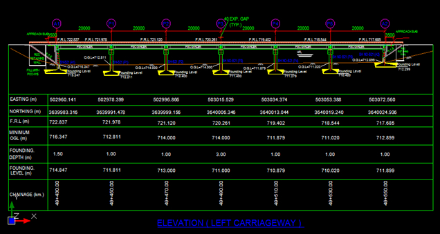
ASTRA Pro provides CAD drawings for Bridge General Arrangements (GAD)

The General Arrangement Drawing (GAD) in ELEVATION with Most informative details on Original Ground Level, Depth & RL of Foundations, Coordinates for Easting and Northing of the Control Line, Bore Holes numbers, expansion joints etc.
Page 5 off 36
British Standard HA & HB Loading following BD 37/01 in ASTRA Pro

British Standard Design of RCC Deck Slab

Page 6 off 36
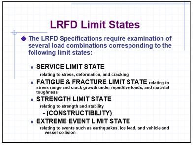
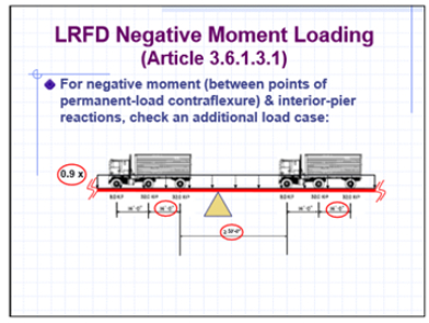
American Association of State Highway and Transportation Officials (AASHTO) for Load Resistance Factor Design (LRFD)

Page 7 off 36
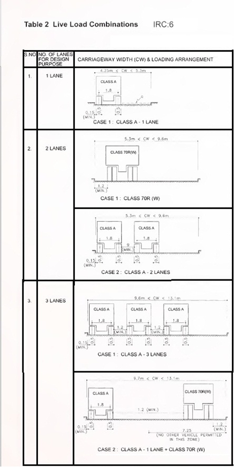
IRC 6 Class Load Combinations
Page 8 off 36
Input for Live Loads for either IRC 6 Class or BD 37/01 or AASHTO-LRFD Combinations is very simple in ASTRA Pro

For RCC ‘T’ or PSC ‘I’ Girder the Main Long Girder is designed with applied Loading

Page 9 off 36
Bridge Design - RCC ‘T’ Girder Bridges for various Spans on British Standard Eurocode 2 and IRC 112

Structural Detailing and complete set of sample CAD drawings are provided with the Detail Design Calculations. Detail information for Construction are also provided in the Drawings

Page 10 off 36
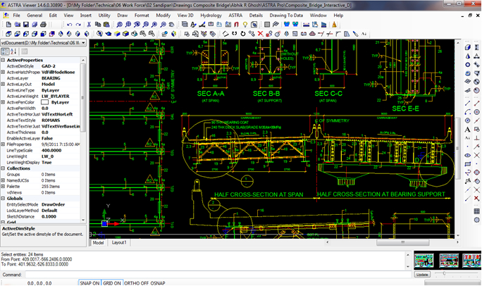
Bridge Design - Composite Bridges with RCC Deck Slab and Steel Plate or Box Girders is designed with Shear Connectors etc. with step wise detail design calculation report and editable structural detail drawing

Construction drawings for Composite Road Bridge with Steel Plate Girder and RCC Deck Slab
Page 11 off 36
Bridge Design – Design of Composite Bridge in Curved Alignment
For Trucks heavily loaded with stone aggregates, sand, marble slabs, cement bags, steel members etc. when negotiates curve the centrifugal force is very high. If the transverse force is considered same as straight bridge, by ignoring the effect of centrifugal force then the design of the Bridge and Bearing is incorrect resulting fall of the curved span.
The essential considerations in this design are:

The related editable CAD drawings for Steel Plate or Box Girder are provided to convert as per design.

Page 12 off 36
Orthotropic Analysis of Composite Bridges: Design of Continuous and Curved Three-Span Composite Bridge with Steel Girders and Concrete Deck Slab may be done with Orthotropic Analysis as per British, AASHTO-LRFD and IRC Standard.

Model View by Graphical User Interface (GUI): View of Model for Orthotropic Analysis for Multi-span Continuous Curved Spans with various options as available on the left panel of the GUI Window.

Page 13 off 36
Bridge Design – Pre Stressed Concrete (PSC) ‘I’ Girder Bridges for various Spans
Bridge Design with ASTRA Pro for Pre-Stressed Concrete Girder Bridge Superstructure is done by receiving user input data in dialog boxes relevant to the desired structure and Loading and obtaining Bending Moments, Shear Force etc from Structural Analysis for DL + SIDL loading + Moving Load by ASTRA Pro using Standard or User defined Vehicle in 1/2/3 or more lanes of moving load at user given increments

Pre Stressed Post Tensioned Concrete Girder Bridge with detail step wise design calculation report and complete set of sample CAD drawings are provided convertible to design drawings.

Page 14 off 36
Bridge Design – Design of Pre-stressed Concrete (PSC) Box Girder Bridges for Elevated Road Corridors and Metro Rails with Detail step wise design calculation report and editable CAD drawings.
The procedure starts with Analysis for DL, SIDL, Live Load (Multi lane vehicle moving load), then stepwise design considering temperature, creep shrinkage etc. for Flexure, Shear including Blister Blocks etc. and finally producing editable CAD drawings with relevant structural & construction details.

The detail step wise calculations are provided in MS-Excel Worksheet.

Page 15 off 36
Balanced Cantilever Bridge ‘ASTRA Pro – Premium’ version features for Construction of Balanced Cantilever Bridge by using Cast-in-Place Segmental PSC Box-Girders along with reports on Structural Analysis and Design, a set of (approx. 100) Sample Editable CAD Drawings for construction of Balanced Cantilever Bridge.

Balanced Cantilever Bridge
Concept for “Model Analysis-Design-Construction” of Balanced Cantilever Bridgee
The module contains the ‘Method Statement’ about the work sequence for the construction of Open Foundation, Piers and Superstructure of Balanced Cantilever Bridge. For the design the software ‘ASTRA Pro Premium’ is used, and a set of editable sample drawings are provided with software ASTRA Pro Premium, this software may be downloaded from its company website www.techsoftglobal.com. After downloading the software may be installed in the system. The software provides analysis, design on analysis and sample editable CAD drawings under the section ‘Drawings’.
Page 16 off 36
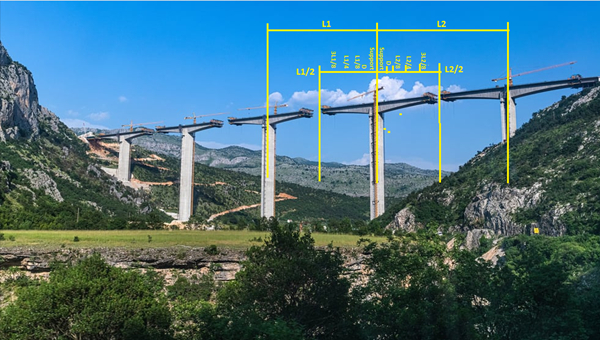
Bridge Design - Design of Cable Stayed Bridge is done with PSC Box Girder and Stay Cables with Non-linear Stage Analysis.
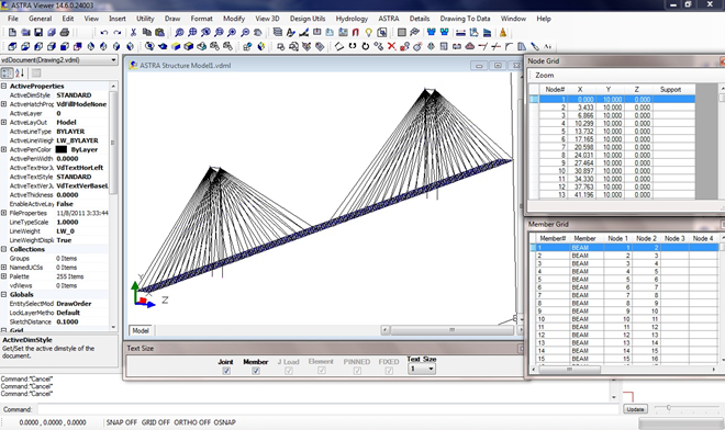
The General Arrangement drawing is provided for PSC Box Girder Deck with Steel Towers

Page 17 off 36
Bridge Design - Design of Extradosed Cable Stayed Bridge is done with PSC Box Girder and Stay Cables with Non-linear Stage Analysis.


Cable Profile and Most Comprehensive Set of Sample Construction Drawings

Page 18 off 36
Bridge Design - Steel Truss Open Web Girder Bridges with Self Weight Computation, Superimposed Dead Load, Vehicle Live Load, Analysis for Member groups, Structural design of Top Chord, Bottom Chord, Vertical &, Diagonal members, Stringer Beam, Cross Girders, Top & Bottom Chord Bracings with Built up sections and production of complete volume of Text Report on Load Computation, Analysis for Truss & Beam Members and Structural Design.
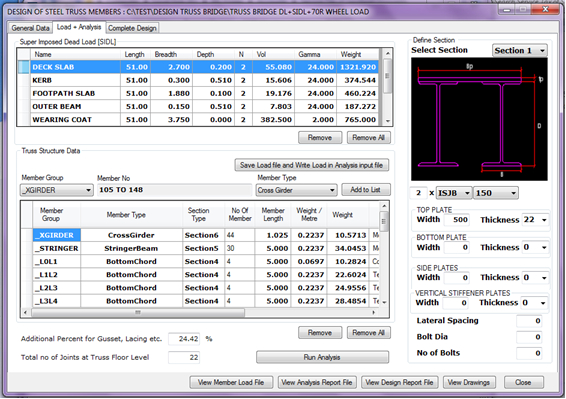
Steel Truss Bridge design with Fabrication/Shop drawings in editable CAD form

Page 19 off 36
The Design of Steel Truss Highway / Railway Bridges In ASTRA Pro the design of Steel Truss Road / Railway Bridges are done in largest form compared to various works presently available. The Detail Calculation for Design of Lacings, Bolted / Riveted / Welded Connections with Gusset Plates, Detail Report for Load Computation, Structural Analysis, Structural Design and production of Complete set of Structural Steel Fabrication detail drawings in CAD

Steel Truss Bridge design with Fabrication/Shop drawings with Details of Member Connections in editable CAD form
Page 20 off 36
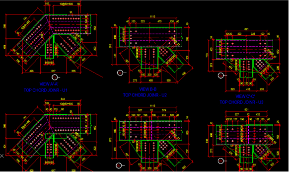
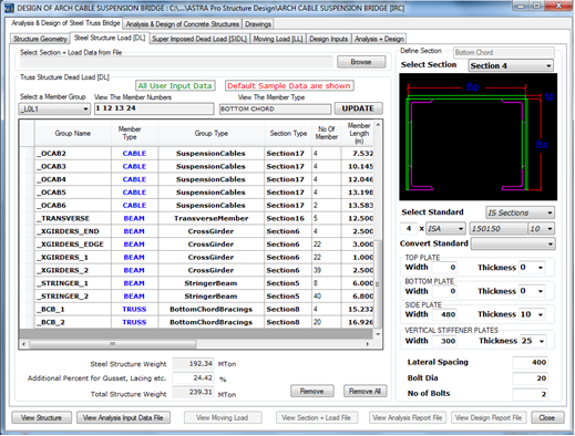
Bridge Design - Steel Arch Cable Suspension Bridge

Member group wise standard or Built up sections may be defined
Page 21 off 36
Bridge Design - Rope Cable Suspension Bridge

The Design of Steel Tower for Rope Cable Suspension Bridge is available with detail construction Drawings.

Page 22 off 36
Bridge Design - RCC Bridge Abutment with detailed design calculation on span lodged and dislodged conditions and taking seismic effects with Structural Detail Drawings in editable CAD form.

Bridge Design - RCC Bridge Pier with RCC Pier Cap and RCC Open Foundation for Fixed Load, Live Load, Seismic Force, Water Current Force with Structural Details CAD Drawings.

Page 23 off 36
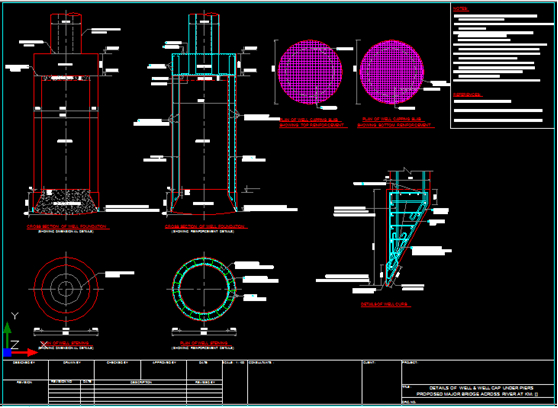
Bridge Design - RCC Well Foundation
With detailed design calculation with Scour Depth, Foundation Depth etc.
Bridge Design - RCC Pile Foundations for bridges from soil structure interaction and structural capacity. The pile capacity is determined from Skin Friction and End Bearing considering the pile passing through various soil strata, next Structural design for reinforcements. The CAD drawing contains design based structural detailing.

Page 24 off 36
Bridge Design - RCC Box Culverts
RCC Box Underpasses with earth cushion and without approach slab to the top slab.
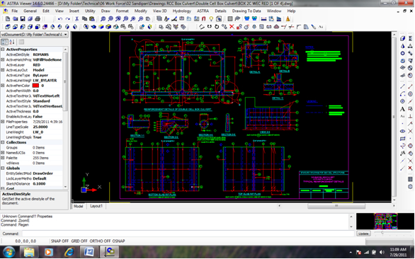
RCC Box Culverts / Underpasses without earth cushion and provision of approach slab on the top slab.

Page 25 off 36
Bridge Design - RCC Slab Culverts / Pipe Culverts / RCC Slab Bridges

RCC Pipe Culverts (NP3 or NP 4) with detail design calculation report and Drawings for new construction or widening of RCC Pipe Culvert with drawings in editable CAD form.

Page 26 off 36
Bridge Design - Seismic Restrainers
In case of transverse force larger than the capacity of Bearings the Seismic Restrainers may be provided on Abutment / Pier, Details of Seismic Restrainers/Stoppers are provided as CAD drawing.

Details of Subsoil Exploration with processing of all related Soil Testing results and Graphical Plotting are available in section known as Geotechnics

Page 27 off 36
Bridge Design - Stream Hydrology
Stream Hydrology is computed in details from Terrain Topography by transforming Transverse marcator data to Universal Tranverse marcator (UTM) data, Referring to WGS84 origin and directly downloaded from Shuttle Radar Topography Mission (SRTM) without Topo maps. Discharge Location at Bridge is measured from farthest point of the River for water discharge at the Bridge location. The environment is 3D CAD, fully compatible to other CAD softwares.
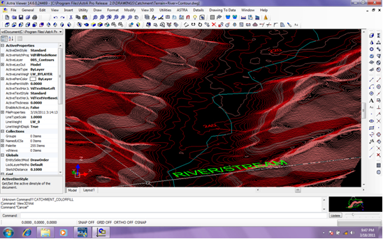
Synthetic Unit Hydrograph is plotted by comparing sum of discharge for 1 hour interval of Time and volume of 1 cm direct Runoff. The Hydrological Calculations for obtaining Scour Depth and Founding Depth for Bridge Foundations are also available.

Page 28 off 36
ASTRA Pro has Optional Suite for RCC Tunnel Lining with Shotcrete, Steel Ribs, RCC Portals.
ASTRA Pro has detail structural analysis and design of Tunnel Lining with RCC Portal, Steel Ribs and RCC Tunnel Lining with shotcrete by evaluating RQD & Rock Mass Rating (RMR).

ASTRA Pro Tunnel Structure Design provides facilities for Geological Mapping and Design of Support System by Rock Bolting, Wire-mesh/SFR Shotcrete (C-25 Grade Concrete), RCC Lining (C-30 Grade Concrete).

Page 29 off 36
ASTRA Pro has Optional Suite for Reinforced Earth Walls
ASTRA Pro Structural Design features for Analysis and Design of Reinforced Earth Walls by using Polymer Geostrips (BS 8006).

A complete set of Sample GADs and Structural drawings are provided to guide the users.

Page 30 off 36
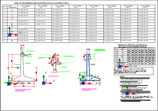
Design of Structures – Design of RCC Retaining Wall as Cantilever and Propped Cantilever, sample CAD drawings are provided for general arrangements and structural detailing.
ASTRA Pro has Optional Suite for design of Box Underpasses and GAD for other Underpasses


Page 31 off 36
Analysis and Design for RCC Framed Buildings, ASTRA Pro features for Analysis, Design, BoQ and Construction Drawings for RCC Framed Buildings

The Building design facility is unique for structural engineers with various facilities for viewing and printing detail Reports, Force Diagrams and Construction Drawings. Design of RCC Slab, Beam, Column and Footings are done with Step by Step detail Report, relevant to Design Standards, Bill of Quantity and complete set of construction drawings.

Page 32 off 36
ASTRA Pro Features for design of Transmission Towers for Analysis with Cable Load, Wind Load and Seismic Load combined for twenty four predefined load cases and Design of Members and Joints.

Transmission Towers for transmission lines from Thermal, Hydroelectric, Gas, and Wind Turbine generated electric power plants and power grid substations.

ASTRA Pro features for Analyses & Design of Transmission Line, Cable Car and Microwave Towers

Page 33 off 36
ASTRA Pro Structural Design features for Analysis and Design of Reinforced Cement Concrete and Pre Stressed Concrete Jettys with Pile Foundation, Long and Cross Girders and Deck Slab.


Page 34 off 36
ASTRA Pro has very powerful static and dynamic Structural Analysis suit featuring:

ASTRA Pro is menu driven, extremely simple, easy to learn & use and ensures fast productivity in shortest possible time, by watching Tutorial Videos as Multimedia movies, referring to Users Manual, Design Manual and Quick Reference Guide.

Page 35 off 36
Your name, Your full address, contact/Whatsapp number, Product Name, Number of Licenses (Discount is offered for Multiple Licenses)
Mrs. Sangeeta
Techsoft Engineering Services (I) Pvt. Ltd., (An ISO 9001:2015 Company)
Mobile/Whatsapp: +91 9331 9330 39, Tel: +91 33 4603 6129. +91 33 4008 3349
Email: techsoftinfra@gmail.com, techsoft@consultant.com, info@techsoftglobal.com
Web site: www.techsoftglobal.com
The Text Book
Title: Computer Aided Bridge Engineering,
Pages: 381
Publisher: Nova Science Publishers, New York, USA
ISBN: 978-1-68507-413-5
Publisher, for Book, Software and Tutorial videos,
Web page: https://novapublishers.com/shop/computer-aided-bridge-engineering-detail-design-of-pre-stressed-concrete-i-girder-box-girder-bridges/
Purchase book from the publisher (Strongly recommended)
Contact: Ms. Lisa Gambino, Email: marketing@novapublishers.com
Software used: ASTRA Pro (Standard used AASHTO LRFD, Eurocode2, IRC 112, IRC 6)
Download ASTRA Pro, Users Manual, Design Manual etc. from website: www.techsoftglobal.com,
Download Book Tutorials from web site: www.roadbridgedesign.com
Tutorial videos: https://www.youtube.com/channel/UCLY751jDWngqMfhKrlRcVwA/playlists
Email: techsoftinfra@gmail.com

(An ISO 9001:2015 Company)
Mobile/Whatsapp: +91 9331 9330 39
Tel: +91 33 4008 3349, +91 33 4603 6129
Website: www.techsoftglobal.com
Email: techsoftinfra@gmail.com, techsoft@consultant.com
Page 36 off 36
 Previous