
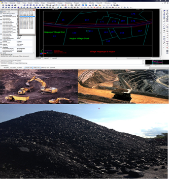
HEADS Site - Mining software provides various facilities for Mining Project Applications. HEADS Site – Mining maintains land acquisition record data in MS-ACCESS database system, It processes Topographical and Spatial Survey data accurately for DTM, Estimation of Stock-pile quantity, Traverse Survey and most economic site preparing with Site Leveling and Grading. The developed land may be used effectively for excavations for the Mining Projects. There is usage of advanced technologies with satellite applications for measurements of the excavation and stockpile quantities.
Cloud based Process / Storage / Sharing facilities are available as optional. On procuring multiple licenses, say, four licenses, and installing at four different locations anywhere in the country/world, the project name, user name and password may be shared with those four license locations. They all can access cloud server to view the design and drawings, modify, re-process, download, upload the work at the cloud storage ‘Techsoft Drive’.
Web site: www.techsoftglobal.com
Email: techsoftinfra@gmail.com, techsoft@consultant.com
Tel: +91 9331 9330 39, +91 33 4008 3349, +91 33 4603 6129
Page 1 off 16

Page 2 off 16
Introducing HEADS SITE The versatile software For Mining Project Applications
We are pleased to introduce to our versatile software HEADS Site for Mining Project applications featuring Traversing, Land Record Management for Site Development. Complete range of processing of various survey data for DTM, Contouring with measurements of Excavation and Stock-pile Quantity, The detail Technical Specification is described in following sections for your reference.
HEADS Site (Mining) is CAD based software and has full range of Survey applications. It handles various Survey data starting with Traversing by closing error corrections by Bowditch, Transit, Closed Link, EDM.
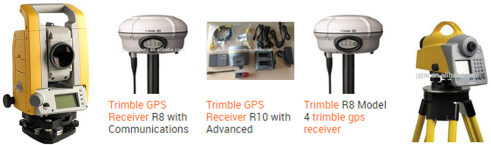
HEADS Site is effective to use ground data by carrying out Topo-survey with Total Station instrument to develop the DTM by Triangulation, Contour, Conversion from TM (Survey) to UTM (GPS) Coordinates, and preparing ground sections in CAD Drawings.
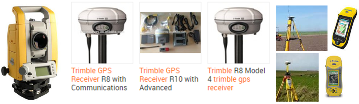
HEADS Site features for using satellite images with Google Earth to plan for aerial usage of the site and downloading ground elevation data from satellite with Shuttle Radar Topography Mission (SRTM) by Internet without any Field Topo Survey.
HEADS Site is features for maintaining, retrieving Land Data Records with various details useful for Land Acquisition and Information purposes, by using MS-ACCESS database systems with ‘mdb’ files and making the data compatible MS-Excel as ‘xls’ files. The land record data is connected with the land drawings by intelligent CAD system which is in-built in the software HEADS Site.
HEADS Site has full range of applications for Site Leveling/Grading projects, Earthwork quantity estimation for Cut & Fill, Mass Haul Diagram, defining of working platforms etc.
HEADS Site has applications to measure the quantity of any irregular shaped Excavations commonly required in Open Cast Mines Mines, with elevation data, DTM, Contouring, Measurement of Quantities etc.
HEADS Site has applications to measure the quantity of any irregular shaped Stock Piles commonly required in Mines, with elevation data, DTM, Contouring, Measurement of Quantities etc.
HEADS Site has powerful Tunnel design facilities using scan survey data in Trimble Robotic Total Station Format, With various Plan Profile Cross Section drawings it provides information on volume of Cut Quantity, Undercut, Overcut, Payline etc. with essential details in Bored & Design Cross Sections in CAD drawing forms.
HEADS Sit> may be effective in your projects to experience the provisions available for various work. We request you to visit our web site www.techsoftglobal.com for downloading Installation Setup of the Trial Version, Various Tutorials, Tutorial Videos etc. You may call us or write to us, in case you want to discuss on any matter.
HEADS Site (Mining) Setup and Tutorials are available for download from our web site www.techsoftglobal.com, and process the Example data following the steps in the Tutorial guide.
Page 3 off 16
HEADS Site: Mining Project Applications
Applications in mining projects need effective software system to create and modify the application as desired to finally produce the best deliverables for the projects. HEADS Site is the most effective tool for such needs as one stop solution with latest satellite technology based as well as manual survey applications.
Survey Applications
Digital Terrain Model
Land Record Management
Site Leveling and Grading
Stockpile Quantity Measurement
Open Cast Excavation Measurement
Design of Tunnel Project
Page 4 off 16
HEADS SITE SURVEY APPLICATIONS
Processing of Traverse Survey Data
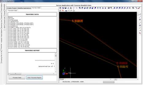
HEADS Site generates Traverse Report describing corrected Traverse and its coordinates with closing error corrections by Bowditch, Transit and Closed link, with EDM applications.
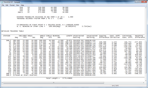
The HEADS Site CAD view of drawing with uncorrected and corrected Traverse and its coordinates.
Page 5 off 16
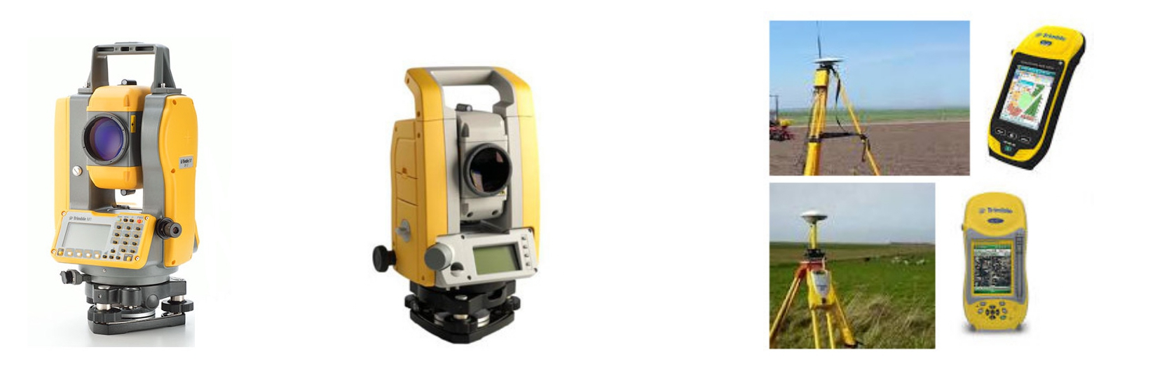
Processing of Total Station Survey Data
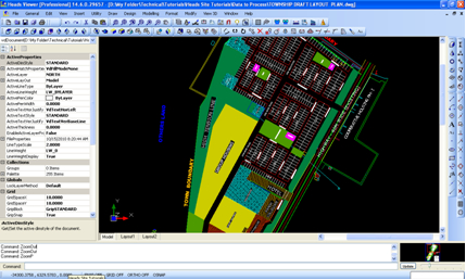
HEADS Site software uses Total Station Survey Data for processing Topographical details most effectively and economically in various Mining Projects for Site Leveling and Grading which is the primary job for Land Development. The developed land is used for platforms for the excavation projects, along with Land Record Management etc.
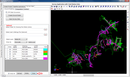
HEADS Site prepares Survey Base Plan or Ground Model from the ground survey data with Total Station. By selecting drawing feature symbols from CAD Block library, the various texts obtained from the surveyors are also placed correctly in the Base Plan drawing. The drawing is made in CAD layered system and is compatible to AutoCAD and other popular CAD softwares.
HEADS Site develops the Digital Terrain Model (DTM) by using the Total Station survey data by Triangulation and subsequently processed for contouring. The area may be identified by site reconnaissance survey and by using Topographic maps along with satellite imageries. The ground elevation data may be either obtained by Total Station Survey or by downloading from SRTM (Shuttle Radar Topography Mission) by using internet. User may procure the computer program Global Mapper to download ground topography data from internet.
Processing of Autolevel Survey Data
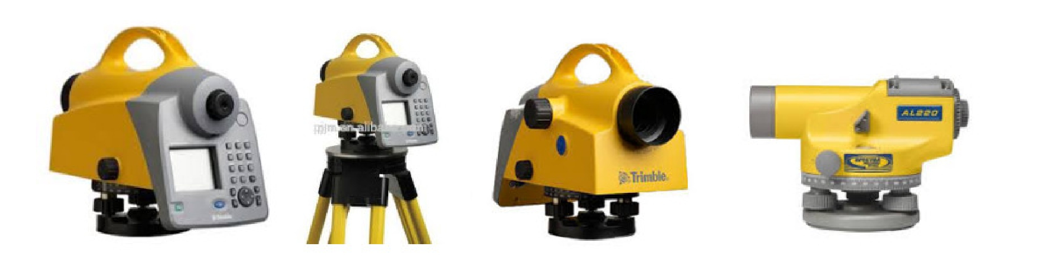
The Autolevel data contains Chainages at a regular / constant interval, the distances on the cross section on either side of the centre point 0.0, left side in ‘-ve’ & right side is ‘+ve’ and the elevations (Z) at all distances on either side of the centre point. The data do not have Easting (X) and Northing (Y) at these points where (Z) is available. So, to get Easting (X) and Northing (Y) at these points an alignment is to be defined, which passes through the centre point at ‘0.0’ of each cross section. Referring to this alignment the program will obtain the X & Y Coordinates of each point on the cross section, this helps in making Triangulation, Digital Terrain Model and finally the Contours of the ground. Only the survey base plan drawing by digital mapping will not be created from ground model, which needs Total Station data for reading various features like Houses, Drains, Electric Poles, Boundary walls etc. on the ground.
Page 6 off 16
Processing of Bearing Line Data
The Bearing Line method of survey is very widely used in creating of foothill traverse. Every hilly terrain commonly has hill on one side and valley on the other side. In Bearing Line Survey the traverse passes through the foothill side, which changes its side with respect to the traverse to stick to the hill.
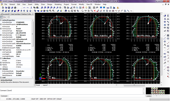
Processing of Robotic Total Station Data
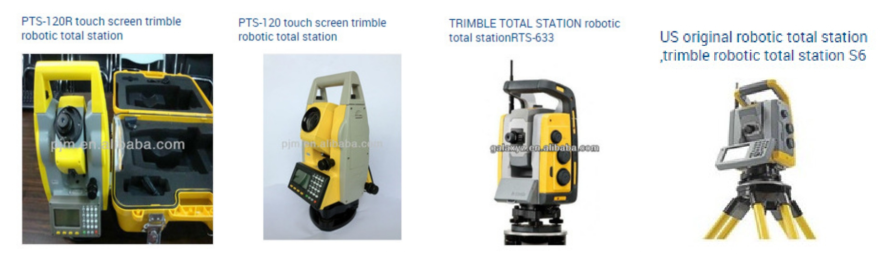
The Robotic Total Station survey data is very widely used in the construction of Bored Tunnels. This is to be noted that the survey is carried out after the boring is done for the tunnel, by following the design horizontal alignment, vertical profile and proposed cross section for the tunnel. The survey data is used to estimate the actual boring against the design cross section of the tunnel. At every chainage the As-Biult and Design Cross Sections are plotted. From the cross sections the ‘Under Cut’ and ‘Over Cut’ quantities are computed by comparing the as-built against the design cross section. Some times in case of excessive overcut the cut quantity is considered up to certain extent outside the design cross section, which is marked as the ‘Pay Line’. Proper measures are to be taken to restore all the over cuts and to remove unwanted soil/rock at the under cuts to match the bored cross sections with the design cross section. All these actions can be done by using the Robotic Total Station survey data and thus processing by HEADS Site to generate cross sections and quantities for Design Cut, As-built Cut (Under Cut & Over Cut) and the Pay Line, also by creating CAD drawings and detail report.

Page 7 off 16
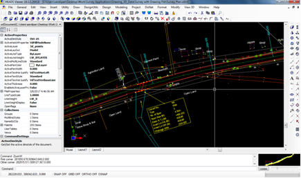
Processing of Drawing File in 3D to extract ground data
The survey plan drawing is made in 3 Dimension and the processing is done to extract the Layer wise x,y,z data of various features of the drawing. The data is saved as Text data in Total Station format and created model with string labels taking from the layer names by saving in the model files.
Ground Modeling
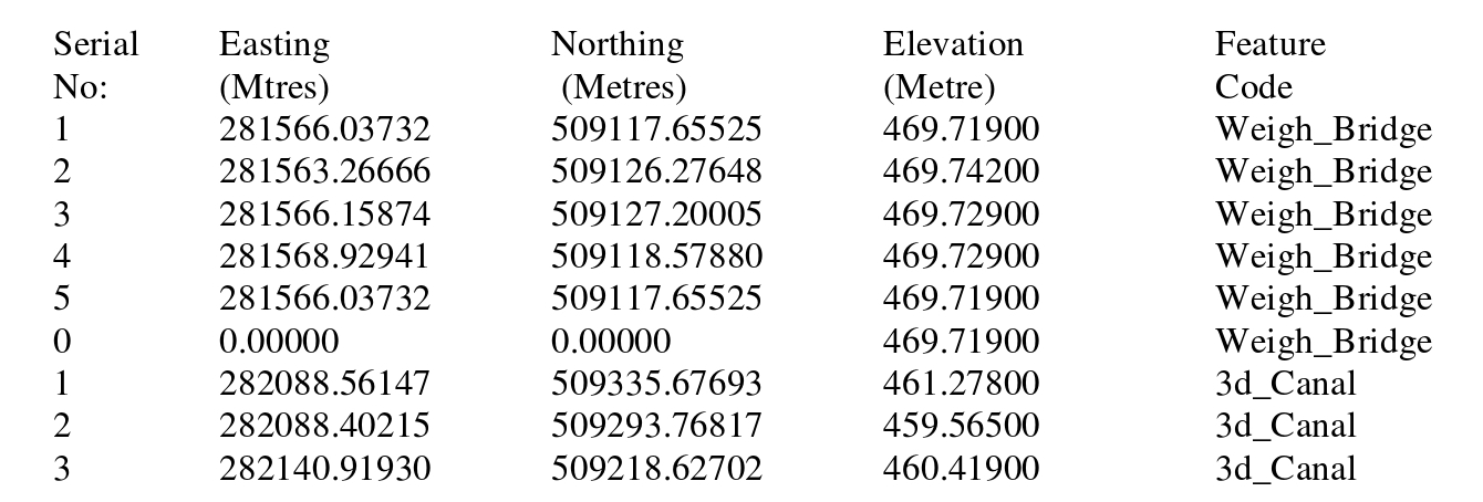
The data in the Total Station survey data file must be made available in the following format and saved as a text file (for example SURVEY.TXT) which can be opened in ‘Notepad’. It has five columns of data, when a data record with Serial No. ‘0’ is met (as after Serial No. 5) then it discontinues the last feature and reads a new feature (from Serial No. 1) in the Ground Model.
Page 8 off 16
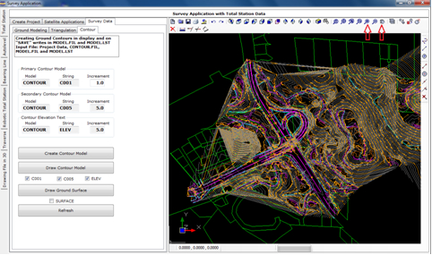
Triangulation and Contours
The model Name, String Label and increments for primary, secondary and Text are set with default names & values. If the ground is of flat nature then user has to reduce the primary contour increment as 0.5 or 0.1 to get contours for the relatively flat ground. The secondary contour increment is always five times of increment of the primary contours. Texts for contour elevations are displayed on the secondary contours.
Land Record Management System
Relational Data Base Management System (RDBMS with MS Access) is used with HEADS Site CAD Viewer
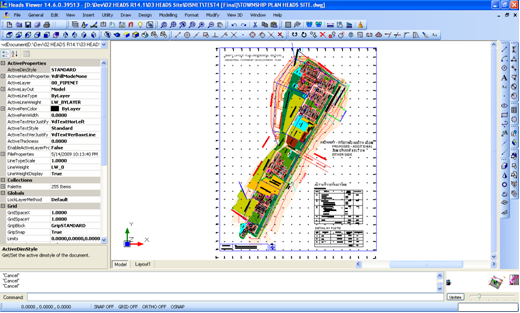
For any site development project for Township, Industrial Plants, Airports, Housing projects the Acquisition of Land for the site is the next job for preparing for construction. The list of names of the land owners, Land category, Land Plot ID, Plot Number, reference District and State in the country. The owners of the acquired land plots are paid by the project authorities. A proper storage of the details along with land maps are therefore essential for the project. The record details are maintaind in Relational Data Base Management Systems (RDBMS) and all the land maps as CAD Drawings. The built-in CAD engine is highly powerful with complete drafting and editing facilities. The drawings are compatible to AutoCAD and all other popular CAD softwares.
Page 9 off 16
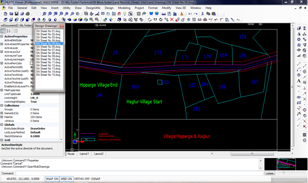
Land records may be Entered and stored in MS Access Database format and CAD Drawings
For any Site preparation the land records and land maps in the existing ground are most essential and properly coordinated by HEADS Site. The establishment of correlation between the database records and the related drawings are extremely useful facilities for maintaining the land records by the users.
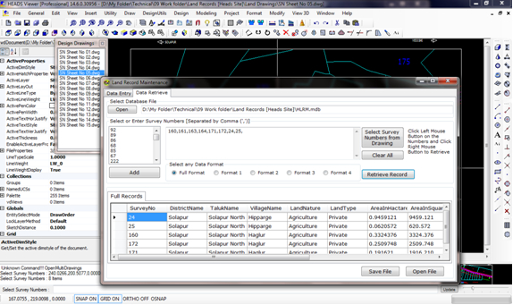
Land records may be retrieved in various specified formats from database or drawings. The relationship between the land map drawings and related records in database management system is highly useful for land record maintenance.
Page 10 off 16
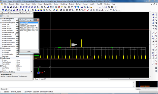
Site Leveling And Grading
For any site development for mining or other projects the Levelling Grading of the site is the job next to acquisition and planning for excavation platforms at various elevations and maintaining desired slopes in 3 dimensional perspectives. The estimation of earthwork in cut & fill is computed accurately by software HEADS Site in well formatted Tabular format following Stations defined along the reference Line. Along with the Digital Terrain Model (DTM) it generates Contours, Elevations on Grids, 3D Surface etc. and all as CAD Drawings. The built-in CAD engine is highly powerful with complete drafting and editing facilities. The drawings are compatible to AutoCAD and all other popular CAD softwares.
For any Site preparation by Leveling & Grading, the existing ground is compared with the Proposed Leveled Ground and the Earthwork is estimated in terms of Cut & Fill.
HEADS Site computes Earthwork for cut and fill as the result of grading of the original uneven ground to construct leveled platforms with roads, drains, slopes etc.
Page 11 off 16
Site Planning
A site planning is done for the mining excavation projects. In recent past the Total Station Survey data was used to record the existing condition and the land use of the site. By using the present advancement of technology in respect of satellite facilities, the various projects are better planned. In HEADS Site the site planning is effectively done with the in-built CAD engine by opening the satellite imagery and enabling the users to make various site planning on the satellite imagery.
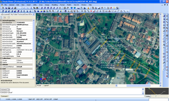
By using Global Mapper the ground elevation data by Shuttle Radar Topography Mission (SRTM) may be downloaded from Internet, without any field survey. This ground data is processed in HEADS Site to develop the Digital Terrain Model (DTM) by Delauney Triangulation and the Ground Contours are created. Next, for site levelling and grading the various excavation platforms are planned and for each excavation platform the horizontal and vertical alignments for the reference axis is designed. Finally cross sections of the platforms are processed to estimate the cut & fill quantities in respect of the existing ground. A well formatted Text Report for quantity estimation and Mass Haul diagram are generated.

Page 12 off 16
Open Cast Mining Applications
Mining applications involves Survey Applications for Traversing with closing error corrections, Ground Model, Digital Terrain Model (DTM), Contour, Land Acquisition with Land Record Management System and Slope Stability Analysis as general applications available with HEADS Site. Additional special applications for Mining are for the measurements of excavation quantity in Open Cast Mines and measurement of Stockpile Quantity. Use of satellite data from Shuttle Radar Topography Mission (SRTM) downloaded with Global Mapper and thus processing the data by HEADS Site for quantity measurements effectively uses the advanced technology.
Measurement of Excavation Quantity in Open Cast Mines
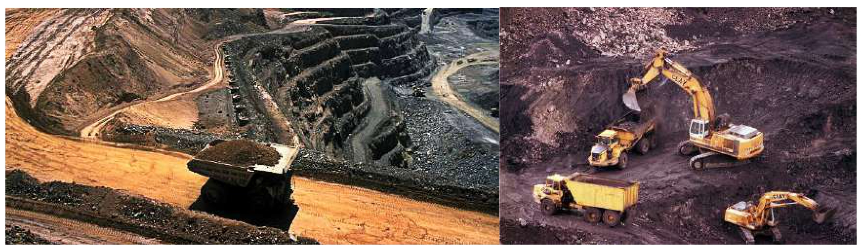
The two main methods which are used for coal extraction are surface mining and underground mining. The methods used to extract coal depend on the geology of the coal. Open cast mining is usually called open-pit or open-cut mining. According to the Berkeley Laboratory for Automation Science and Engineering, open cast mines are designed before a mining operation begins. Engineers divide the area to be mined into large cubes, which are excavated one at a time until the entire mining project is completed. The blocks are mined in a predetermined order to maximize profits and minimize environmental impacts.
Measurement of Stockpile Quantity
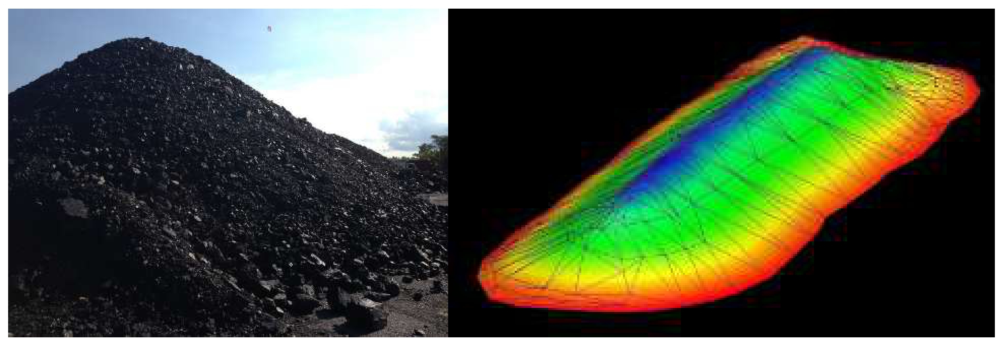
The area of horizontal plane is computed at top most elevation, and there is no quantity is estimated at this top most elevation. Next, the area is computed for the horizontal plane at next lower elevation, and the quantity is estimated as the average of the previous and the current areas and by multiplying by their difference of elevations. Every time the current volume and the cumulative volume are computed and written in the report.
This process is continued up to the lowest elevation of the Open Cast Pit, at this lowest point the cumulative volume gives the volume for the excavated pit under consideration. The report is also opened in ‘Notepad’ this helps in taking printout of the report. The difference between two volumes made by obtaining survey data (or satellite downloaded data) at certain interval of time gives the current volume of excavation during that period.
Page 13 off 16
Tunneling Applications
Tunnels are constructed to create travel routes without disturbing the existing surface and environment, ensure uninterrupted work. CAD based design for Horse Shoe/Semi Circular / Circular / Rectangular / Custom type Tunnel Sections,
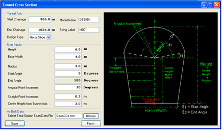
The Boring Cut Quantities are estimated for Design Cut, As Built Cut, Over Cut and Under Cut. The “Pay Line” outside the design section is also defined to include the desired amount of overcut in the measurements. Ready to Plot and Editable CAD Drawings are created as the output.
Page 14 off 16
Analysis for Stability of Slopes
Slope stability analysis is performed to assess the safe design of a human-made or natural slopes (e.g. embankments of dam, dyke, road, cuts, open-pit mining, excavations, landfills etc.) and the equilibrium conditions. Slope stability is the resistance of inclined surface to failure by sliding or collapsing. The main objectives of slope stability analysis are finding endangered areas, investigation of potential failure mechanisms, determination of the slope sensitivity to different triggering mechanisms, designing of optimal slopes with regard to safety, reliability and economics, designing possible remedial measures, e.g. barriers and stabilization.
Successful design of the slope requires geological information and site characteristics, e.g. properties of soil/rock mass, slope geometry, groundwater conditions, alternation of materials by faulting, joint or discontinuity systems, movements and tension in joints, earthquake activity etc. The presence of water has a detrimental effect on slope stability. Water pressure acting in the pore spaces, fractures or other discontinuities in the materials that make up the pit slope will reduce the strength of those materials. Choice of correct analysis technique depends on both site conditions and the potential mode of failure, with careful consideration being given to the varying strengths, weaknesses and limitations inherent in each methodology.


Page 15 off 16
HEADS Site – Mining Release 24 Package:
Each package contains the following items:
License Types for Each Product:
License Option1: The single user "Professional License" is made on individual user's name.
License Option2: The single user "Enterprise License" is made on company's name, for one year free email based technical support.
All the Licenses have same Features content of the software.
Purchase and Licensing for Each Product:
Each software License is Web based. Purchase Order/Request is to be sent to Techsoft with complete address, Post Code and Telephone number. Next, we shall send the Invoice with our Bank Account details for making the payment. Customers may make the payments by Cards by using menu ‘Purchase’ at web site www.techsoftglobal.com, or by Online Transfer to the account of Techsoft as mentioned in the Invoice. No payment should be done without Invoice and after making payment customer has to inform Techsoft about mode of payment.
After making the payment customer has to run the installed software and select menu item ‘File >> Enter License Activation Key’. The ‘Computer ID is detected, user has to click on ‘Send Mail’ in internet connected condition. Next, we shall send the License ‘Activation Key’ within next two working days to the customer by mail. The user has to copy the ‘License Key’ and paste in the box in software menu item ‘File >> Enter License Activation Key’. The license will be activated in the PC/Laptop. During the validity of the license it can not be shifted to another PC/Laptop. The License is for one year, for renewal, after each year user has to pay the annual subscription within 15 days from expiry of the license.
(An ISO 9001:2015 Company)
Mobile/Whatsapp: +91 9331 9330 39
Tel: +91 33 4008 3349, +91 33 4603 6129
Web site: www.techsoftglobal.com
Email: techsoftinfra@gmail.com, techsoft@consultant.com
Page 16 off 16
 Previous