
The versatile software for engineering design of Railway, Rail Yard, Crossings, Points, Metro Rail, LRT, MRT, Mono Rail projects
[Operating Systems: Microsoft Windows 10/11, 32 / 64 Bit, Minimum 4 GB RAM, 100 GB HD Space]
HEADS Rail is best for CAD based Railway Engineering and Design. Our product HEADS Rail for design of railway tracks is available with very high technological standard and at a very reasonable price for carrying out various work related to railway detail engineering projects. The HEADS Rail - Technical Specification may be downloaded from website.
Cloud based Process / Storage / Sharing facilities are available as optional. On procuring multiple licenses, say, four licenses, and installing at four different locations anywhere in the country/world, the project name, user name and password may be shared with those four license locations. They all can access cloud server to view the design and drawings, modify, re-process, download, upload the work at the cloud storage 'Techsoft Drive'.
Web site: www.techsoftglobal.com
Email: techsoftinfra@gmail.com, techsoft@consultant.com
Mobile: +91 9331 9330 39
Tel: +91 33 4008 3349, +91 33 4603 6129
Page 1 off 20

Page 2 off 20
Application of Railway Design software HEADS Rail in developing effective Railway Transport System

The development of effective rail transport system is the primary need of any developing country and the upgrading of existing railway network system is essential for the developed countries as the capacities of railways are reached to saturation level with the passage of time.
The railway development involves very high degree of attention by the project Authorities as well as by the Consultants, Engineers and Contractors. Any mistake May result in expenditure of a few millions which could have been avoided. Normally the design of route alignment and the ancillary structures decide the cost of a railway project and for this job the best experienced manpower and best available tools must be deployed.
The best available tools essentially Include the selection of most appropriate Railway Design software which must be capable of handling any type of situation and the best manpower is the engineers and other technical staff who have the essential educational background and sufficient experience in working for similar projects and most essentially have required level of training to use high quality design software products.
HEADS Rail is applicable for Metro Railways for design speed of 135 Kilometres per Hour or more, Standard gauge, Broad Gauge, Meter gauge, any defined maximum “Cant” at Super elevated sections giving inner edge rotation, Curves with Clothoid Transitions, Earthwork Estimation, Construction Drawings, Design of rail Yards, Design of Points, Crossings, Track Diversion in case of Repairing, Curvature, Train Resistance & Haulage Capacity on Grades and Track stresses.
Page 3 off 20
NEXT GENERATION TECHNOLOGY
Presently there are two varieties of Software available based on two basic concepts namely: “Template” and “String” modeling. The first group of products are simple to learn and handle but have substantial limitations in handling today’s demand for railway geometric design, Whereas software using “String” modeling technique is efficient for railway projects involving Cost Control for new rail routes, double tracking of existing routes, Surface Correction & Strengthening, Design of multi-alignment railway junctions, points, crossings, yards, varying cross-sections, with or without service corridors appearing anywhere along the length, design of Underground Metro Rails, Elevated Metro Rails, Mono Rails, Hill routes having special considerations, Railway Tunnels with sharp turns ranging from 90 to 180 degrees. In HEADS Rail the conventional String technique is modified to make the production more efficient. HEADS Rail has full power CAD engine to view and edit drawings as desired. The drawings are compatible to all commonly used CAD softwares.
It is simple in HEADS Rail to transform the Surveyors coordinates into Global UTM / GPS Coordinates using in-built CAD engine, next the transformed drawing may be opened for conversion to KML/KMZ file to open in Google Earth to plan for Green Field alignments, Bypasses and Realignments as larger area with existing Land use are visible. Even the Original Ground Elevations along with Easting & Northing Coordinates are available from the satellite images without doing the topographic survey at the field.

Fig 1 Power of CAD based design technology
HEADS Rail software from TechSOFT Engineering Services is based on “String” modeling technique and is today’s established name in offering the users all the facilities described above. It accepts Topographical Survey data from Total Station, Auto level, GPS, Topo Maps, Aerial Photograph, Satellite Imagery Remote Sensing etc. It offers the facility to use Digitized Topo Maps in case of absence of Topographical Survey data. Detailed tables are also generated for Traverse Survey, EDM Survey and Co-ordinate conversion from Spherical (Lat-Long) to Rectangular (Easting-Northing) which is a very complex process and is hardly available in market available products. HEADS Rail has its own CAD engine and is best appreciated for its Power, Completeness, Versatility, Fastest Processing, Simplicity and Exchangeability of Input and Output with other commonly used Railway Engineering software of similar kind and all popular CAD software.
HEADS Rail itself is a marvel in the history of railway engineering softwares. The main power of HEADS Rail lies in its CAD engine which produces sophisticated construction drawings for the project. This achievement is in addition to its engineering output with best possible accuracy and widest range of coverage in any Railway engineering project.
Page 4 off 20
Salient Features cum Technical Specifications:
Applications for Land Survey , DTM and GPS:
String based software generally starts functioning using the Detail Survey data primarily using Total Station instrument. But there are a lot more tasks to do in an actual project, before obtaining the Detail Survey data. These essential tasks are most commonly the Obtaining two Reference points at every 5 Kilometres using GPS instrument, Using the GPS Co-ordinates carrying out Traverse Survey by using Total Station instrument, Obtaining Correct Traverse Co-ordinates by Bowditch or Transit or Closed Link method followed by installation of Reference Pillars to help in carrying out the Detail Survey. These are essential tasks for any Detail Survey project. The GPS data is more reliable if obtained in the form of Longitude and Latitude (than in the form of East North), the Long Lat data may be converted to Easting and Northing by using correct parameters specific to the location in the globe. Once the GPS data are available in Easting and Northing, these become usable by the Total Station instrument. The data conversion needs correct parameters and the process is also quite cumbersome. Additionally the Correction of Traverse Co-ordinates to install Reference Pillars also needs considerable amount of time and effort by the engineers at the project site. Here comes HEADS Rail has the complete one stop solution for all these requirements by the site engineers at simplest effort. Being a String based software HEADS Rail is very versatile to handle various site situations and eventually comes as an ‘All Complete Solution’ for various Railway Engineering projects.
Applications for Engineering Design :
Applications for Construction:
Page 5 off 20
Special Points on Technical Specifications
Page 6 off 20
Survey facilities with latest technologies by using GPS Technology are best processed in HEADS Rail
The instrument GPS (Global Positioning System) is based on Satellite technology. If the Survey is done in Surveyors TM Coordinates the data and Survey base Plan may be created in TM Coordinates, which are not applicable universally by any user, for example Contractor. So the Drawing & Data available in TM Coordinates are to be converted to UTM (Universal Transverse Marcator) Coordinates. Both the conversions (Drawing & Data) are possible in HEADS range of products to make KML / KMZ files which may be superimposed on Google Satellite images (Version 2010) to view the existing Land use and Merits/Demerits of each alignment options.

It is simple in HEADS Rail to transform the Surveyors coordinates into Global UTM / GPS Coordinates using in-built CAD engine, next the transformed drawing may be opened for conversion to KML/KMZ file to open in Google Earth to plan for Site Layout, Green Field alignments, Bypasses and Realignments as larger area with existing Land use are visible. Even the Original Ground Elevations along with Easting & Northing Coordinates are available from the satellite images without doing the topographic survey at the field.
Digital Terrain Model & Contouring: The area may be identified by site reconnaissance survey and using Topographic maps and satellite imageries. Elevation data may be downloaded from SRTM (Shuttle Radar Topography Mission) and contours have been generated for the entire area under the study. This enables the users to produce Plan, Profile, Cross Section Drawings and BoQ of the design work without carrying out Topographical Survey at field.

Page 7 off 20
Survey work with advanced instruments & Techniques are best processed in HEADS Rail

It processes Survey data available from Total Station, Auto Level, GPS, Compass Survey and develops Ground Model, Digital Terrain Model (DTM) by Delauny Triangulation, Ground Contours, Ground Sections at user given primary & secondary intervals, 3D Surface with rendering, Ground Long and Cross Sections, Digital Mapping. The Digital mapping facility enables the users to prepare Survey base Plan drawings over Google Pictures using the CAD engine of HEADS Rail.
The Survey reference pillars can be installed by obtaining Traverse coordinates with closing error correction by Bowditch, Transit & Close Link methods, EDM Survey, Coordinate Transformation from WGS84 to Lambert Conformal Conic Projection (Long Lat to East North) and the reverse with Spheroid Everest 1956. For any Site preparation, the existing ground is compared with the Proposed Leveled Ground and the Earthwork is estimated in terms of Cut & Fill. The Triangulation is done with best possible accuracy, using spatial data, developing DTM, drawing Contour Topography, Digital Maps and establishing Area / Zone wise reference points to facilitate various construction activities in the future
Satellite Images or Aerial Photographs for various regional planning and design may be used efficiently for on screen interactive design over these images and is considered as most advanced facility by the use of latest technology

Page 8 off 20
SURVEY BASE PLAN or GROUND MODEL is prepared from the Total Station Survey Text data and by selecting drawing feature symbols from CAD Block library, the various texts obtained from the surveyors are also placed correctly in the Base Plan drawing. The drawing is made in CAD layered system and is compatible to AutoCAD and other popular CAD softwares for any further editing/drafting. Contours and DTM, with Ground sections are also produced as Reports and CAD drawings for Plan & Profile, Cross sections. This saves the time significantly in preparation for the Detail Engineering Projects.
Built-in CAD System of HEADS Rail provides most useful and effective facility for various design work in modern Railway/Metro Rail Transit Projects. The availability of Google images is a remarkable achievement in recent time. HEADS opens the images and upon setting actual Easting & Northing coordinates in the image the route alignment may be tried for various options against the existing land use of the region and finalized for best techno-economic option.

CAD based interactive Alignment Planning on Satellite or Google Images
IN BUILT CAD ENGINE FOR INTERACTIVE DESIGN AND DRAWINGS
HEADS Pro is the masterpiece for its various applications in railway engineering projects. It enables the engineers and professionals to produce the best in their work by suiting the site condition most accurately and economically.

CAD based interactive alignment design and modification at any time
Page 9 off 20
DESIGN OPTIMIZATION FOR COST MINIMIZATION
Advanced technology is available in HEADS Rail to Optimize the Vertical Profile of the proposed railway for the Earthwork in Cut & Fill in case of new construction or double tracking projects.

Design Optimization for Cost Minimization
DESIGN OPTIMIZATION DECRIBED IN PROFILE LONG SECTION DRAWING
Facility is available in HEADS Rail to design Vertical Profile based on the calculated Haulage Capacity and Grades of the proposed railway for the Earthwork in Cut & Fill based on available Haulage capacity.

Optimized Vertical Profile in Long Section Drawing
Page 10 off 20
CONSTRUCTION DRAWINGS FOR RAILWAYS

Cross section Drawing in CUT

Cross section Drawing in FILL
Page 11 off 20
DESIGN OF Rail YARDS of types Diamond, Pyramid etc.

Diamond Type of Rail Yard [1]
Design of Alignment, Profile, Switch details etc. For Mono Rail

Design of Mono Rail
Page 12 off 20
DESIGN OF POINTS and CROSSINGS

Design of POINTS

Various design elements in POINTS
Page 13 off 20
esign of Alignment, Profile and other features for Elevated sections of Metro Rail

Design of Elevated sections Metro Rail
Railway and Metro Rail Tunnels - Design of Alignment, Profile and other features for Tunnel sections
HEADS is the ideal solution for the engineering design and construction of vehicular and Railway Tunnels either Bored or Cut & Cover type

Design of Railway / Metro Rail Tunnels
Page 14 off 20
TUNNEL CONSTRUCTION: The design Audit is extremely important during the Tunnel construction. Any deviation of the Tunnel axis from the original alignment must be rectified as soon as it is detected. For an early detection appropriate instrumentation is essential.

In curved sections it is essential to check the lateral clearance in horizontal & vertical directions at various locations and elevations. Because of the superelevation/CANT calculated from the curve radius and design speed, the tilt is more at greater height & distance. This may lead to reduction of the lateral clearance between the coach top edges and the side walls of the Tunnel. 'HEADS Rail' creates such most essential Tunnel cross section drawings taking points at various offset distances and elevations in the cross section to create the dynamic coach profiles and make the audit possible in true sense. In Tunnel engineering 'HEADS Rail' is the capable software to produce engineering reports and drawings with most of the information required and with best sophistication.

Coach Profile for Construction of Tunnels for Metro Rails
Page 15 off 20
Processing of TRIMBLE Robot Total Station Data
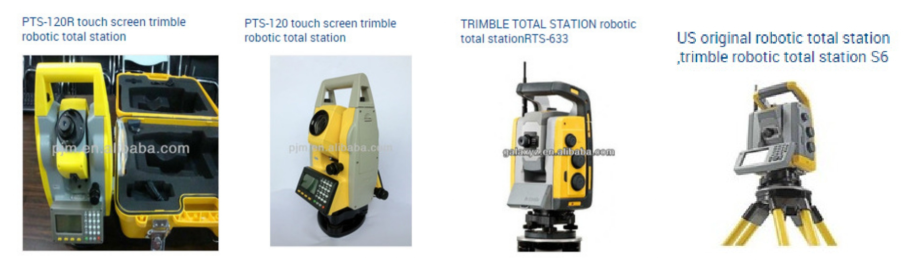
The TRIMBLE Robot Total Station survey data is very widely used in the construction of Bored Tunnels. This is to be noted that the survey is carried out after the boring is done for the tunnel, by following the design horizontal alignment, vertical profile and proposed cross section for the tunnel. The survey data is used to estimate the actual boring against the design cross section of the tunnel. At every chainage the As-Biult and Design Cross Sections are plotted. From the cross sections the ‘Under Cut’ and ‘Over Cut’ quantities are computed by comparing the as-built against the design cross section. Some times in case of excessive overcut the cut quantity is considered up to certain extent outside the design cross section, which is marked as the ‘Pay Line’. Proper measures are to be taken to restore all the over cuts and to remove unwanted soil/rock at the under cuts to match the bored cross sections with the design cross section. All these actions can be done by using the Robotic Total Station survey data and thus processing by HEADS Pro to generate cross sections and quantities for Design Cut, As-built Cut (Under Cut & Over Cut) and the Pay Line, also by creating CAD drawings and detail report.

Page 16 off 20
Tunnel Lining - Software ASTRA Pro alongside software HEADS Rail features for the Structural Design of Railway Tunnel Lining with Rock Bolting, Shotcrete, Steel Ribs and Wire mesh for Tunnel and Portals. These are important facilities in this software system. Provides CAD based checking of Coach Profile inside the Tunnel. All the design work produces editable full set of sample construction drawings in CAD format.

The Boring Cut Quantities are estimated for Design Cut, As Built Cut, Over Cut and Under Cut. The "Pay Line" outside the design section is also defined to include the desired amount of overcut in the measurements. Ready to Plot and Editable CAD Drawings are created as the output.

Page 17 off 20
For railway of length 100 or 200 km it is indeed tedious to layout sheets for every 1 km length, on full length PLAN drawing, to cut the full length drawing into 1 km pieces, as required to produce the PLAN-PROFILE drawings. The same is now automatic for user selected sheet size, scale, start and end chainage, length in each sheet, etc. This is now saving significant time to create a large number of PLAN drawings containing desired length of the road.

Upon finalizing the project drawing sheet by editing the sample drawing sheet, the cutting of PLAN drawing of full length into pieces of desired length and finally the insertion of PLAN and PROFILE parts of every kilometer of railway is now just a mouse click only. The intelligence in HEADS Rail is the best in the industry for its power and accuracy.

Page 18 off 20
Land Acquisition Record Management in MS Access Database format and CAD Drawings
For any Site preparation the land records and land maps in the existing ground are most essential and properly coordinated by HEADS Rail. The establishment of correlation between the database records and the related drawings are extremely useful facilities for maintaining the land records by the users.

Land records may be retrieved in various specified formats from database or drawings. The relationship between the land map drawings and related records in database management system is highly useful for land record maintenance.

Page 19 off 20

(An ISO 9001:2015 Company)
Mobile/Whatsapp: +91 9331 9330 39
Tel: +91 33 4008 3349, +91 33 4603 6129
Web site: www.techsoftglobal.com
Email: techsoftinfra@gmail.com, techsoft@consultant.com
Page 20 off 20
 Previous